

Thermal Growth Case Study
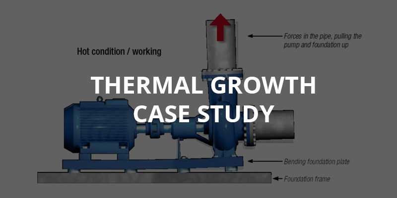
In this case study we will determine the effects of thermal growth on a pumping unit used as part of a manufacturing plants process. This sort of equipment is used in thermal metal treating and needs to perform flawlessly to keep up with industrial production.
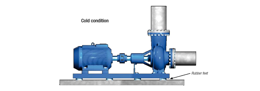
The machine units are mounted on a steel base plate which in turn is supported on special rubber mounting pads and secured to a strong foundation. The manufacturing plant had designed and fabricated this important cooling water system to control the temperature of their electronic instruments.
Report
Hot alignment.
First, we performed a shaft alignment measurement in cold conditions using the thermal growth specification so that we could verify and document the exact position of the motor and pump shafts compared to each other. We then started the machine and when it had reached its maximum working temperature we quickly shut it down and locked it out.
Once again we performed a shaft alignment measurement. By doing this “hot alignment” we could see how the thermal growth had changed the laser alignment. The results were very good matching the calculated thermal growth. We were within tolerance so this could not be a cause for increased vibration levels. Nor would it have caused the damage of the pump shaft.
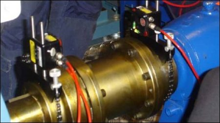
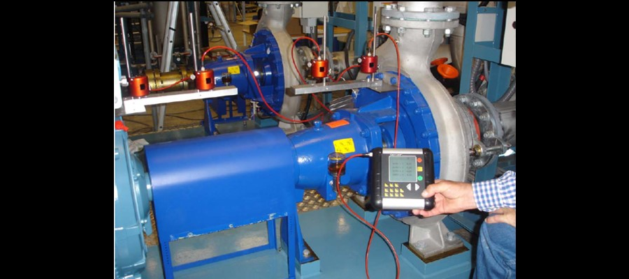
 Although performing a hot shaft alignment gives you a good indication of the thermal growth of the machine units, it does not give you a real time measurement. To do this we then used our D23 Easy-Laser Spin laser transmitter and four D6 Spin-detectors (2 of which are shown in the picture to the right) which we connected in series. We produced two (2) brackets which were mounted on the pump and motor. On each bracket we then mounted two (2) detectors.
The laser transmitter was placed on a stand on the floor and was leveled so that we could read the spirit levels. This allowed us to confirm that the transmitter did not change its position during the measurement. The detectors were then adjusted on the mounting rods so that the beam swept the detector surface in the midst of its range. Program 33 (rotation) was used on the display unit which then showed the four (4) detectors with real time measurement readings at the same time. Next we zeroed set the detectors on the display unit.
Now all we had to do was start the machine units and watch the display and observe the real time measurement.
We could now read how both the motor and the pump changed their position compared to each other. It showed that the rear part of the pump rose 0.019″thou (0,5 mm) and tilted downwards 0.011″ thou (0,3 mm) at the centre of the shaft compared to the centre of the motor shaft. These measurement values did not correspond with the values that we had received in the hot alignment condition.
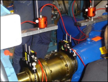
We then decided to investigate whether the base, which is a solid steel plate with the dimensions of thickness 2.4″ (60 mm), width 39″ (1000 mm) and length 78″ (92000 mm), was moving or not. To do this we mounted the four (4) detectors on the base (PHOTO – below left) we wanted to measure and placed the Laser transmitter on another base (PHOTO – below right) which was not being used.

The transmitter was secured by its magnetic base and it was leveled, each detector was set to zero. We then started the motor and ran the machine unit at its full capacity and at its maxim operating temperature. The measurement results showed that the rear part of the base rose 0.019″ thou (0,5 mm) and flexed 0.007″ thou (0,2 mm) in the middle.
Evaluation
All the measurement values that we recorded when the detector was mounted on the motor and pump and the base plate were documented graphically on a paper.
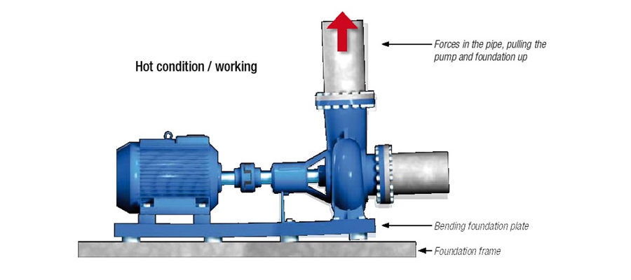
We could then clearly see the position of the pump shaft centre in relation to the motor shaft centre when the machine units were running and under full load. The force of the connecting pipe on the pump lifted the whole base which flexed at the middle. This was the cause of the large offset and angular misalignment between the pump and motor which then created increased vibrations. Based on the facts of the measurement results we recommended that the customer strengthen the base and modify the piping support and also to consider using a flexible joint between the pipe connection and the pump to minimize the force.
Summary
With this information we would like to emphasize that far too many installation technicians focus on the thermal growth of the motor and pump, but they forget the fact that dynamic force very often gives larger alignment error than the thermal growth. In other words one does not always see the true result by measuring the position of the shafts in cold condition and then in warm condition even though this gives good information about the thermal growth. In this case the thermal growth changed the offset of the centre of the shaft 0.004″ thou (0,1 mm ). While the dynamic forces when the machine units were running online changed the offset 0.016 thou (0,4 mm).
About Author
0 comments
Write a comment