While “shaft alignment” is the common term, the correct term would be “shaft to shaft alignment”. However, when we say shaft alignment, it is assumed that we are aligning one shaft to another. What we’re trying to accomplish is the alignment of the rotational center line of one shaft with the other shafts rotational center line. These shafts are usually being held in position by bearings attached to machines such as a pump and motor.
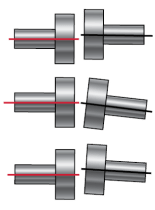 The goal is for these shafts to stay aligned when in operation, at full operating temperature and under load. The sheer torque of running machines will create an offset and angular misalignment, usually a combination of both (see Figure 1).
Many use the term “coupling alignment” which is incorrect. This was an old term used to describe the straightedge and feeler gauge method of alignment. This was normally done without shaft rotation. This method of alignment can still be used as a rough-in process prior to precision alignment, but it cannot achieve the necessary tolerances needed for modern day machines.
Wikipedia describes shaft alignment as “the process of aligning two or more shafts with each other to within a tolerated margin. It is an absolute requirement for machinery before the machinery is put in service.”
Remember – shaft alignment is only one aspect in the machinery installation process!
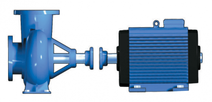
Figure 2
Rotating machines are usually described according to how they are connected to each other. The most common are horizontally mounted machines, usually a pump and motor (see Figure 2). Rotating machines can also be positioned vertically on a flange-mount in some circumstances.
Another type is offset mounted, or cardan-shaft-coupled machines aka universal joints. These often have some type of drive, for example rollers in a papermaking machine. Many people wrongly believe that cardan-shaft-coupled machines do not need to be aligned as accurately. But an angular error in these machines causes a non-linear motion, which causes forces and vibrations in bearings, couplings and seals. In other words, shortens the service life.
Often several machines are connected in line, usually called a Machine Train, for example a gearbox between engine and the driven machine.
A modern shaft alignment system can measure all the above types of machine.
Correctly aligned shafts mean many improvements:
- Increased availability and productivity of the machine = assured production.
- Increased service life of bearings and seals = fewer removal of replacement parts
- Complete seals = less leakage and better working environment
- Optimally utilised lubricant film = less risk of overheating and secondary damage
- Reduced lubricant leakage = less lubricant consumption
- Less vibration = reduced noise level
- Less risk of serious breakdowns = safer working environment
Greater overall savings with fewer spare parts, lower energy consumption and less unscheduled downtime.
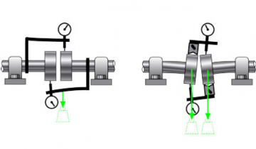
Figure 3
Using a laser-based shaft alignment system is without doubt the best method. Yes, you can use a dial indicator system, however, these systems are fraught with errors. For example:
- Dial alignment takes longer.
- Requires experience/knowledge.
- Calculations are needed
- Dial alignment kits are prone to mounting errors and looseness.
- Dial sag has to be measured and compensated for (see Figure 3).
- Dial sets can not produce documented results of before and after alignment work.
The biggest issue is the human element. This means the transfer of information from what is read on the dial is many times input incorrectly into the calculation.
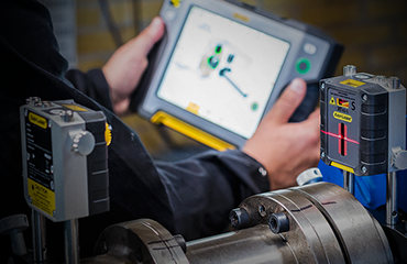
Figure 4
Laser alignment tools (see Figure 4) on the other hand are considerably easier and faster to use (although speed is not an essential factor – repeatable measurements and precise results are the goals). Laser alignment systems also:
- covers many more applications such as Horizontal, Vertical, Spacer shafts, Cardan shaft (universal jointed shaft), etc.
- spans large distances (ie. jackshafts). A basic system will span 3 meters while a professional system will span 20 meters
- have built-in tolerance guidelines including the new ANSI standard.
- takes measurements with as little as 40 degrees of shaft rotation
- can compensate for offsets because of sleeve bearings or thermal growth issues.
Most importantly they can give a documented, detailed report of the installation (see Easy-Laser XT Report example in Figure 5). Because if you have to do a breakdown analysis on this machine and you don’t have this report you will only be guessing as to what was done. For motor shaft alignment tools & equipment contact us.
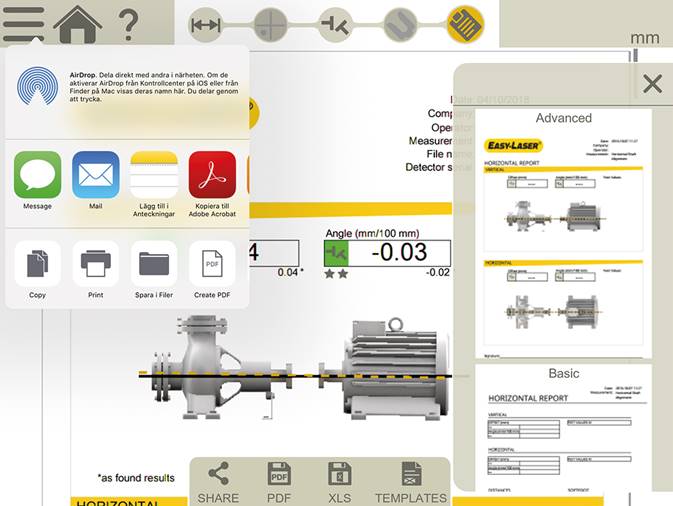
Figure 5
We are Canada’s Master Easy-Laser Distributor
machine, laser, engine, vibration, pump, bear, coupling, shaft alignment, measurement, indicator, tool, vertical and horizontal, drive shaft, sensor, shim, pipe, screw, heat, foot, failure, wear, temperature, manufacturing, transmission, electric motor, rotation, angle, steel, turbine, friction, pressure, lubricant, energy, speed, steam, stainless steel, diameter, stress, noise, torque, gear, downtime, shape, shaft, maintenance, straight edge, feeler gauge, risk, plant, technology, condition monitoring, thermography, beam, asset, nut, management, flange, motion, checklist, propeller, pulley, troubleshooting, rust, distortion, infrared, experience, motor, method, laser shaft alignment, laser alignment, methods, reference, check, thermal expansion, force, bearing, accuracy and precision, fluke corporation, data, wireless, lens, software, consumption, productivity, humidity, rechargeable battery, calibration, inclinometer, user interface, united states, nondestructive testing, quality, interface, camera, brand, backlash, water, electricity, canada, probes, bluetooth, universal joint, bracket, information, ultrasound
Frequently Asked Questions
What are the causes of shaft misalignment?
The main causes of shaft misalignment are the shear torque of running machines, which creates an offset and angular misalignment, usually a combination of both.
How to identify shaft misalignment patterns?
Identifying shaft misalignment patterns involves recognizing common signs such as vibrations, abnormal bearing wear, and coupling issues. Precise measurement tools like laser alignment systems can accurately detect angular and offset misalignment.
Can shaft misalignment cause machine failure?
Shaft misalignment can indeed cause machine failure. Misalignment creates excessive wear and tear on bearings, seals, and couplings, leading to increased vibration, premature failure, and potentially catastrophic breakdown of machinery.
What is the purpose of shaft alignment in machinery?
The purpose of shaft alignment in machinery is to ensure the shafts of connected machines are properly aligned, reducing wear and tear on bearings, couplings, and seals, thereby increasing the overall efficiency and lifespan of the machinery.
What is the benefit of precise shaft alignment?
Precise shaft alignment increases service life of bearings and seals, reduces leakage and noise, and lowers energy consumption, leading to greater overall savings through fewer spare parts and less unscheduled downtime.
How often should shaft alignment be checked?
Shaft alignment should be checked regularly, typically every 6 to 12 months, or whenever a machine is serviced or relocated, to ensure optimal machine performance and prevent premature wear or failure.
What tools are required for cardan shaft alignment measurement?
For cardan shaft alignment measurement, laser alignment tools are required. Laser alignment systems can measure and align horizontal, vertical, and cardan shaft (universal jointed shaft) applications.
How to document shaft alignment results properly?
Documenting shaft alignment results properly involves using laser alignment tools that can provide a detailed report of the installation, including the before and after measurements. This detailed report can help ensure the alignment meets necessary tolerances.
What is the difference between laser and traditional shaft alignment?
The difference between laser and traditional shaft alignment is that laser alignment tools are considerably easier and faster to use, cover more applications, and provide a documented, detailed report of the installation, whereas traditional dial indicator systems are fraught with errors.
How to measure shaft misalignment angles?
Shaft misalignment angles can be measured using laser alignment tools. These tools provide a detailed report of the installation and are easier and faster to use compared to dial indicator systems.
What is the difference between soft foot and shaft misalignment?
Soft foot is a condition where one or more machine feet do not make proper contact with the mounting surface, while shaft misalignment refers to the improper alignment between two coupled shafts.
What are the types of shaft alignment methods?
The types of shaft alignment methods include horizontal, vertical, and cardan shaft (universal jointed shaft) alignments. These methods use tools such as dial indicators or laser alignment systems to measure and correct shaft misalignment.
How to correct shaft misalignment issues?
Correcting shaft misalignment issues involves using precision alignment tools like laser-based systems to precisely measure and correct any offset or angular misalignment between the shafts, ensuring optimal machine performance and reducing the risk of premature wear and failure.
Can vibration analysis detect shaft misalignment?
Vibration analysis can detect shaft misalignment. Excessive vibration levels and particular vibration patterns are indicators of shaft misalignment, and vibration analysis can be used to identify and diagnose this issue.
What is the relationship between cardan shaft alignment and bearing life?
The improper alignment of cardan shafts can lead to increased vibration and forces, which can significantly reduce the lifespan of bearings and other machine components.
What is the role of shaft alignment in preventive maintenance?
Shaft alignment plays a crucial role in preventive maintenance by ensuring proper machine functioning, reducing wear and tear on components, and minimizing the risk of unexpected breakdowns, thereby enhancing overall equipment reliability and longevity.
Can cardan shaft alignment be automated or is it manual?
Cardan shaft alignment can be automated using laser alignment tools, which are more efficient and accurate than manual methods. These tools can measure and document the alignment of cardan shafts, providing precise and repeatable results.
How to perform shaft alignment on rotating equipment?
Performing shaft alignment on rotating equipment involves precisely measuring and adjusting the position of one shaft relative to another to ensure proper alignment. This can be achieved using precision tools like laser alignment systems.
How does temperature affect cardan shaft alignment procedures?
Temperature changes can affect the dimensions of cardan shafts, altering the necessary alignment tolerances. Precise measurements and adjustments may be required to maintain proper cardan shaft alignment as temperature fluctuates.
What are the differences between cardan and traditional shaft alignment?
The differences between cardan and traditional shaft alignment are that cardan shaft-coupled machines experience angular error which causes non-linear motion and forces, whereas traditional shaft alignment focuses on aligning one shaft directly to another shaft.
Can shaft alignment improve machine efficiency?
Proper shaft alignment can improve machine efficiency by reducing vibrations, wear, and energy consumption, ultimately increasing the service life of bearings, seals, and other machine components.
What is the importance of shaft alignment in industry?
Proper shaft alignment is crucial in industry to optimize machine performance, reduce wear and tear, and minimize downtime, thereby increasing equipment lifespan and operational efficiency.
What is the ideal tolerance for cardan shaft alignment?
The ideal tolerance for cardan shaft alignment is critical, as any angular error can cause non-linear motion, leading to forces and vibrations in bearings, couplings, and seals. Precise alignment of cardan shafts is necessary to ensure optimal performance and extended machinery lifespan.
Is laser shaft alignment a one-time process or ongoing?
Laser shaft alignment is an ongoing process, as machines can become misaligned over time due to factors such as thermal expansion, foundation settling, and vibration. Regular laser shaft alignment is necessary to maintain optimal machine performance and prevent premature wear and failure.
What precision levels do alignment methods achieve?
Alignment methods can achieve precision levels within 0.05 mm (0.002 inches) or better when using laser-based alignment tools, which is necessary for modern machine installations and maintenance.
How does misalignment affect machine efficiency?
Misalignment between machine shafts can lead to increased vibration, wear, and energy losses, thereby reducing the overall efficiency and performance of the machine. Misalignment creates additional stresses on bearings, seals, and couplings, leading to premature failure and higher maintenance costs.
What factors influence shaft alignment tolerances?
The factors that influence shaft alignment tolerances include the type of machinery, the speed and load of the machine, the shaft material, and the coupling design. The required tolerances are tighter for high-speed, high-load machinery to ensure optimal machine performance and efficiency.
How do alignment errors impact maintenance costs?
Alignment errors can significantly impact maintenance costs by causing increased wear on bearings, seals, and couplings, leading to more frequent part replacements, unscheduled downtime, and higher energy consumption.
What innovations improve shaft alignment accuracy?
Innovations that improve shaft alignment accuracy include laser alignment tools, which are easier and faster to use than dial indicator systems and can cover a wider range of applications with detailed reporting capabilities.
How does alignment frequency affect machine health?
Proper shaft alignment frequency is crucial for maintaining machine health. Frequent alignment ensures minimal misalignment, which reduces wear and tear on components, extends bearing life, and prevents premature machine failure.
pump alignment, shaft alignment tool, laser shaft alignment, machine alignment, shaft alignment tools, pump alignment tool, coupling alignment, laser alignment tool for pumps, laser alignment report, laser shaft alignment tool, motor pump alignment, cardan shaft alignment, laser alignment, laser coupling alignment, alignment shaft, shaft alignments, laser alignment of couplings