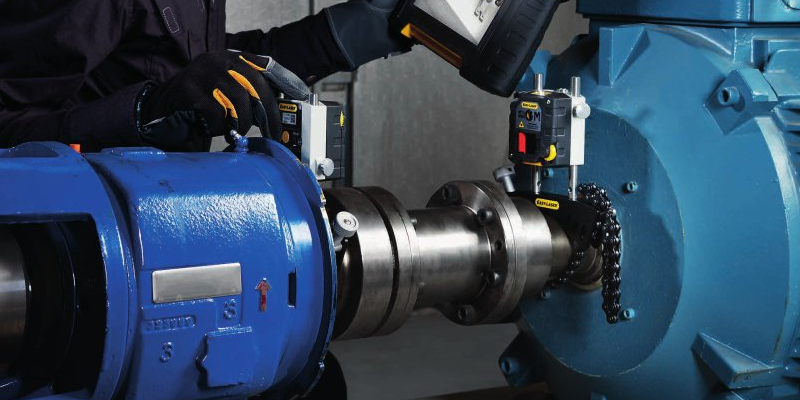
Getting the Right Angle Shaft Alignment
Getting the right angle can pull you out of a jam.
When we think of shaft alignment we usually think of one machine being the stationary and the other machine being the moveable. The normal preference is to use the driven (ie. pump) as the stationary and the driver (ie. motor) as the moveable. The reason behind this is that you don’t want to create pipe strain by moving the pump. Makes sense right? For some who don’t think beyond this, it limits their options.
The reality is that you can move either machine and in fact, in the case of say, a diesel engine that is driving a generator, it’s the driven that is normally chosen to be the movable. However, very often moving a combination of both machines will give you the best option with the least amount of correction.
During our three day MAAD Training Machinery Installation program we can demonstrate this combination move during the reverse-dial indicator shaft alignment section. MAAD is an acronym for Measure, Analyze, Act and Document and that is the process we promote during the training. This training covers it all from nuts and bolts to the geometric measurement of the base. We train participants in shaft alignment using dials and laser systems.
Currently, an organization that is taking the program had asked that we include both Rim and Face and Reverse Dial methods of shaft alignment as well as laser alignment which we accommodated.
One benefit of using the reverse-dial alignment procedure is that we can use the graphical method to calculate the necessary machine corrections. The graph is a pictorial view of the machines shafts which is to scale.
If we set up a graph and draw the machines shaft and leave out the dial plotting points you would have something like this below. The black solid lines represent each of the machines shafts plotted from the dial indicator readings (not shown). The red lines represent the plane of the machines feet (the adjustment points). The dashed line is a target line for traditional alignment graphing/plotting.
We are showing the vertical plane only and the scale we are using is such that going across the page each small box is equal to 1 inch. Moving up and down, each small box is equal to 0.001 inch (1 thou).
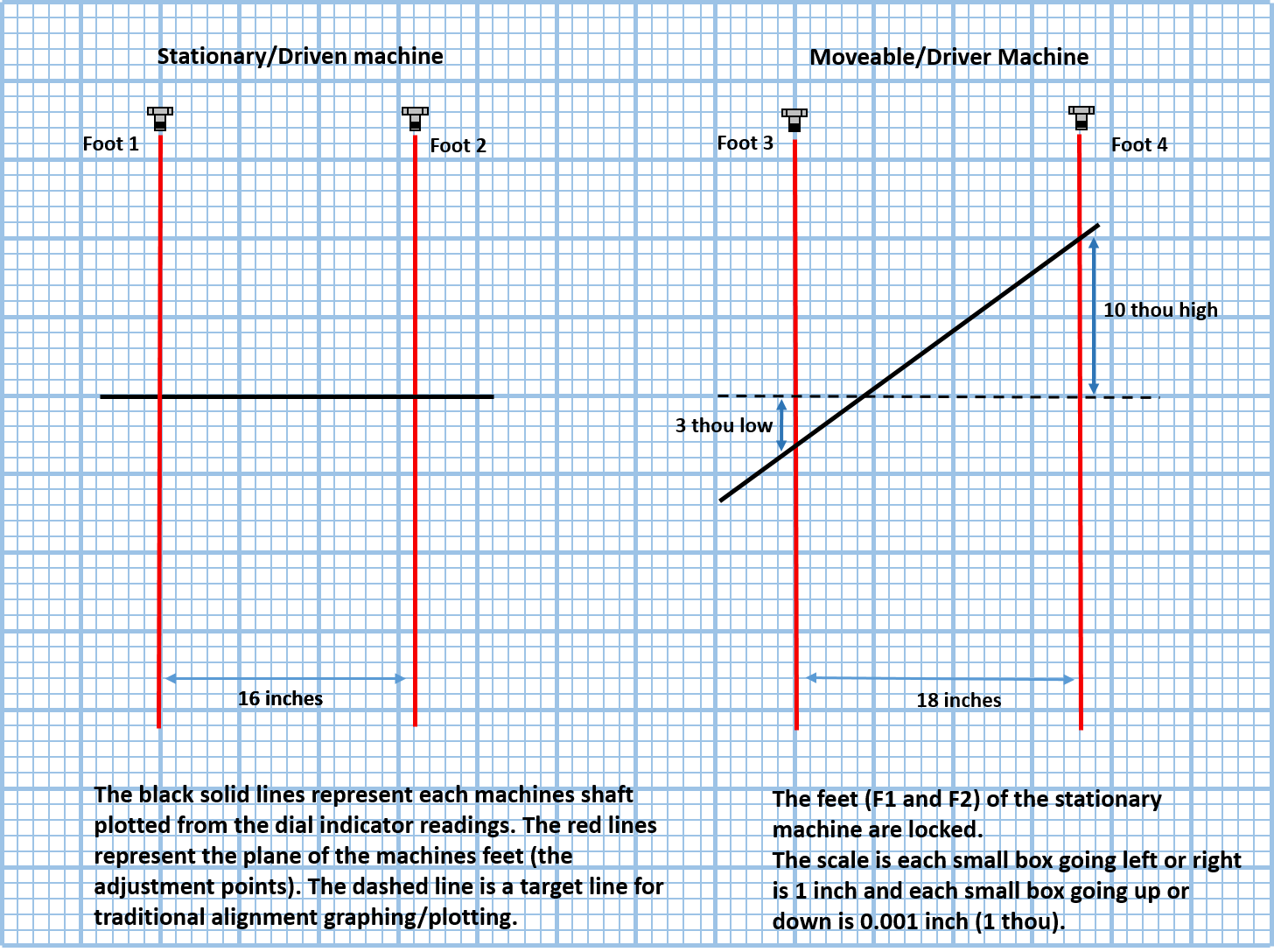
The stationary machine is on the left and as you can see we have 16 inches between the feet. It is drawn in the traditional manor as sitting in a level plane.
The moveable machine is on the right and its position is based on the dial reading taken from each shaft. However, for simplicity we are not showing the plotting points. You can see we have 18 inches between the machines feet and the shaft is low at foot 3 (F3) but high at foot 4 (F4).
Now imagine that we are base bound – a common problem in the real-world. There is no shim under the back feet (F4) and based on this graph, it is telling us that we must lower the back feet by 10 thou. The problem is, however that we cannot lower the machine if there is no shim to take out.
So we have measured the misalignment and now we can use the graph to help analyze the base bound issue. Remember the goal is simply to have these two shaft as one. We need to move one or both to be opposite to each other, in line, the technical term is collinear. To be inline in both horizontal and vertical planes.
Because of the base bound issue, the traditional option is to lift the stationary machine up by equal amounts to be higher than the moveable machine – in this case above 0.010 inch (thou) which is the high point. You would then readjust the movable machine into alignment. However, this is a lot of work and you will be fighting the pipe if the stationary machine is a pump so you are better looking for an alternative option.
The fact is that there is more than just one option. The stationary/moveable method means that the stationary feet are “locked”, and usually fixed in position. However, you can choose which feet to “lock” in any combination so you can achieve your goal of collinear shafts. To see this on our graph we can draw a (green) line from one outbound foot to the other (Foot 1 to Foot 4). We draw the line through the point where the shaft intersects the foot plane. This green line is now our target line.
Now if we view these outbound feet to be the locked pair we can see that in order to achieve our alignment we will have to move the inbound feet up. In this case the Driven (stationary) has to go up 0.003 inch (3 thou) at Foot 2 and the Driver (moveable) has to go up 0.010 inch (10 thou) at Foot 3. Now that’s a lot less work than the first option and it gets you out of the base bound issue.
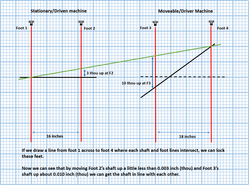
Now can this move cause other issues? The answer is yes it can but let’s continue with the analysis before we make the move. We can see that the front foot of the pump has to go up 0.003 inch (3 thou). If we want to find out how much of an angle we will be introducing by lifting the pump/pipe flange up we will use the rise over run principle. If we divide 3 thou by the distance between the machines feet (16 inches) we get 0.1875 per inch of angle that we will be introducing to this machine. If we multiply that by the distance across the pipe flange, which is let’s say 7 inches, we would be lifting it up 0.0013 inch (1.3 thou) which is very little indeed. Once we are satisfied with our analysis stage, we take action and make the move. But this is only one option – if we draw our line from Foot 2 through to Foot 4 we could tilt the pipe flange down instead.
The point is that you have options when moving machine units and very often a small amount of angle can make a big difference. You need to be able to see and understand this when you analyze the results of your measurement. Understanding dial indicator shaft alignment methods as well as graphing or plotting helps you see the whole view – the bigger picture. This is why organizations like the American Petroleum Institute (API), who have produced their own pump and motor installation standards, highly recommend that tradesmen who use laser systems to align shafts be fully conversant with dial alignment methods.
Now a good laser shaft alignment tool will give you different bolt bound and base bound options such as these examples below.
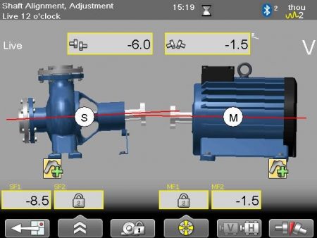
Above, we lock the inbound feet of the stationary (pump) and the inbound feet of the moveable (motor) in the vertical plane. If we were base bound, this would be a good option because we can add shim.
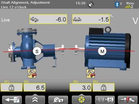
Above, we lock the outbound feet of the stationary (pump) and the outbound feet of the moveable (motor) in the vertical plane. If we were base-bound, this would not be a good option because it’s asking us to take shim out, and there is no shim to take out.
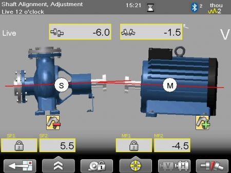
Above, we lock the outbound feet of the stationary (pump) and the inbound feet of the moveable (motor) in the vertical plane.
If you look at the different options you can see the amount of angle you are introducing to the machines – in this case, 1.5 thou per inch with each option. Multiply this by 7 inches (distance of pipe flange face) and you get 0.0105 inch. Yes 10.5 thou – can the pipe handle that much? The way to find out is to measure it and with this style of laser you can actually measure the effects of pipe strain but I will save that for another article.
Remember, the optimum move is the one that meets your needs the best but if we were base bound, option 1 would work the best.
Finally, documentation is a basic requirement for a machines history file. It is also being strongly requested by companies after an alignment is finished. So don’t short change the job. Finish it off by capturing this important information and don’t forget to include your graphs in the documentation and report section.
About Author


0 comments
Write a comment