What’s Your Angle? Working through a common Shaft to Shaft Alignment issue & Documenting the Process
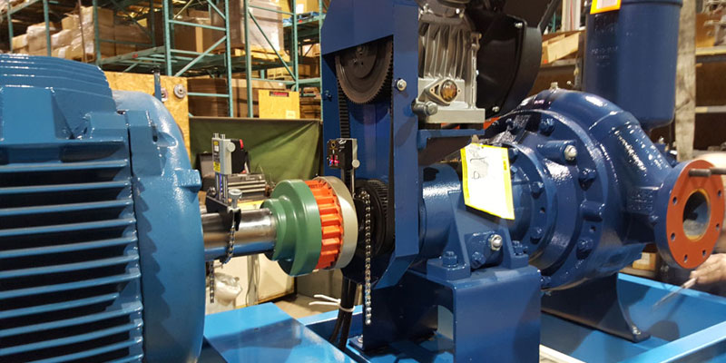
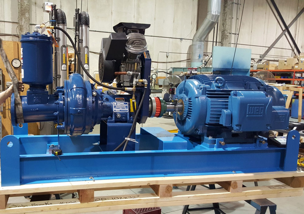
Recently, I was asked to do some consulting/on-the-job training for one of our customers in the Greater Toronto Area. This was a sizable pump supplier & maintenance company that just bought our entry-level Easy-Laser E420 Shaft Alignment tool. They needed to align the two shafts (of the pump & motor) and later commission it into service for their customer. They were packaging the machine units together (bolting the pump and motor to the base frame while aligning the shafts) and it was to be shipped on a skid to their customer. Once the machine units and frame were delivered they were to do a final alignment check after the machine’s base was bolted to the foundation.
It was an important customer of theirs who required a report of the aligned set up, so they called me in to make sure everything went smoothly with their newly purchased shaft alignment tool. They wanted to make sure all the correct documentation was in order, so all the right boxes could be ticked off. This is great practice because more and more now customers are asking that documentation is added to alignment work. It is a piece of history that you can store in your records so you can see how the machines were left when you decide to work on it next time.
When I arrived, the pump already had about 50 thou (0.050 “) under each foot so that we would have sufficient space in which to move the motor without being base-bound. We put our laser shaft alignment tool on each machine units’ shafts – the stationary laser unit on the pump and the moveable laser unit on the motor. We then took our measurements and the results showed that the motor needed to come down about 30 thou (0.030 “) in the front feet and 40 thou (0.040 “) in the back feet. There was no shim at all under the motor so we were base-bound.
Now, we could have added more shim under the pump raising the shaft centerline higher than the motors. In this way, we would only have to add shim under the motor for a good alignment, right? Not so fast. I had run into this problem before iqs still base-bound. I kept adding more and more shim under the pumps feet until finally I could align the shafts without dropping the motor. Because of this experience, I knew all I had to do was change the angle of the pumps shaft slightly and I would be able to adjust my motor properly. For more information on an example of this issue and how it is dealt with click here and check out the article called “Getting the Right Angle…”

I ended up adding 20 thou (0.020 “) to the front feet of the pump, changing the angle only. Once the pump was again tightened down, we did another shaft alignment and we were able to add some shim to the motor and get a good alignment.
This was a small issue but a common one. One of the most important parts of this process is the documentation. It is important that we take note of what happened during the shaft alignment measurement and shaft alignment process so that we can learn on the job, so the next guy aligning the machine units will know what happened the last time.
- The customer required a detailed report on how the machine has been left while bolted down. Some things that should be included in your Documentation Reports are:
- Measurement Data including File name, Date, Operator Name, Measurement Program or Instrument used, Measurement units, etc.
- Machine Data including types of machine units and distances between laser units and feet
- Softfoot measurements
- Thermal growth values (if available)
- Tolerances used
- As Found and As Left measurements taken for both vertical and horizontal planes,
- Notes to describe the measurement process in full.
For an example, of what a report might look like, email us at info@benchmarkpdm.com and we will send you an example!


0 comments
Write a comment