Frequently Asked Questions
What are the benefits of precise machine base flatness?
Precise machine base flatness ensures optimal machine performance, minimizes vibration, and extends the lifespan of critical components, leading to improved productivity and reduced maintenance costs.
How does base flatness affect machining accuracy?
Base flatness is crucial for machining accuracy, as any deviations can lead to inconsistent tool paths, affecting part precision and quality. Proper flatness measurement and adjustment of the machine base are essential to ensure optimal machining performance.
What is the tolerance for base flatness in machining?
The tolerance for base flatness in machining typically ranges from 0.05 to 0.1 mm, depending on the size and complexity of the machine base. Achieving optimal flatness is crucial to ensure proper functioning and alignment of machinery components.
How to correct machine base flatness deviations?
Correcting machine base flatness deviations involves using precision measurement tools like laser shaft alignment systems and swivel lasers to accurately assess the flatness and identify areas needing adjustment. Appropriate adjustments can then be made to the machine base to achieve the required flatness.
Which instruments measure base flatness to nanometer precision?
Instruments that measure base flatness to nanometer precision include laser shaft alignment tools and advanced swivel lasers. These high-precision measurement systems can detect and analyze even the smallest deviations in surface flatness.
What are the limitations of measuring base flatness?
The limitations of measuring base flatness include the potential for environmental factors, such as temperature and vibration, to affect the accuracy of the measurements, as well as the need for skilled technicians to properly conduct the assessment.
Can machine base flatness be improved after installation?
Yes, machine base flatness can be improved after installation by using precision measurement tools and adjustment techniques to identify and correct any deviations from the desired flatness specifications.
Can base flatness be measured using a straightedge?
Base flatness can be measured using a straightedge. However, a straightedge provides a limited measurement area and may not capture the full flatness profile of the machine base, which is better assessed using more advanced tools like a laser shaft alignment system.
How to achieve precise machine base flatness?
Achieving precise machine base flatness involves using specialized tools and methodologies, such as laser shaft alignment tools and D22 swivel lasers, to accurately measure and analyze the flatness of the machine base, enabling the identification and correction of any irregularities.
How do you ensure accurate base flatness measurement?
Accurate base flatness measurement is ensured by utilizing precision measurement tools like laser shaft alignment systems and swivel lasers, which provide detailed analysis of the machine base's surface topography and deviation from a planar reference.
What methods are used to measure base flatness?
The methods used to measure base flatness typically involve precision measurement tools such as laser shaft alignment systems and swivel lasers. These tools enable accurate assessment of the flatness by capturing detailed measurements across the machine base surface.
How often should base flatness be measured?
The frequency of base flatness measurement depends on the application and environment, but it is typically recommended to measure it annually or whenever a significant change or issue is observed in the machine's performance.
Can base flatness be improved through surface finishing?
Yes, base flatness can be improved through surface finishing. Proper surface finishing techniques, such as precision grinding or lapping, can help reduce surface irregularities and enhance the overall flatness of machine bases.
What are the consequences of inaccurate base flatness measurement?
Inaccurate base flatness measurement can lead to issues such as premature machinery wear, vibration, and misalignment, which can result in decreased productivity, increased maintenance costs, and potential equipment failure.
What is the relationship between flatness and machine stability?
The relationship between flatness and machine stability is that a flat machine base is crucial for ensuring the stability and accurate performance of machinery. Precise flatness measurements help identify and address any issues that could compromise the machine's stability and functionality.
How does base flatness affect part functionality?
The flatness of a machine base directly impacts the functionality of parts produced on that machine. Uneven surfaces can cause parts to be misaligned, leading to inconsistent performance and quality issues.
What is the role of flatness in machine performance?
The flatness of a machine base is crucial in ensuring optimal machine performance. Proper flatness allows for accurate alignment and minimizes vibrations, contributing to improved efficiency, reliability, and longevity of the machinery.
How to maintain machine base flatness over time?
Maintaining machine base flatness over time involves regular inspections, monitoring for changes, and making necessary adjustments or repairs to ensure the base remains level and stable. This helps maintain the accuracy and performance of the machine.
What is the impact of flatness on machine vibration?
The impact of machine base flatness on vibration is significant. Uneven surfaces can cause mechanical components to become misaligned, leading to increased vibration, accelerated wear, and reduced machine performance.
Can laser interferometry measure base flatness?
Laser interferometry can be used to accurately measure the flatness of machine bases. This precision measurement technique is effective in evaluating the surface flatness of industrial equipment to ensure proper alignment and performance.
How to inspect machine base flatness during installation?
Inspecting machine base flatness during installation involves using precision measurement tools such as laser shaft alignment and swivel lasers to accurately assess the flatness of the machine base, ensuring proper alignment and stability for optimal performance.
What are the consequences of poor machine base flatness?
Poor machine base flatness can lead to misalignment, increased vibration, and premature wear of machinery components, resulting in reduced equipment performance, efficiency, and lifespan.
How to measure machine base flatness accurately?
Measuring machine base flatness accurately involves using precision measurement tools like laser shaft alignment tools and swivel lasers to assess the flatness across the surface, identifying any high or low spots that could impact machine performance.
What tools are used to check machine base flatness?
The tools used to check machine base flatness typically include laser shaft alignment tools and swivel lasers, which can provide precise measurements and assessment of the machine base's flatness.
Can machine base flatness affect production quality?
Machine base flatness can significantly affect production quality, as uneven surfaces can lead to misalignment of machinery, causing issues like vibration, premature wear, and inconsistent product output.
What is the importance of measuring base flatness?
Measuring the flatness of a machine base is important to ensure the proper alignment and operation of the equipment, which is crucial for its performance, efficiency, and longevity.
What is the ideal tolerance for machine base flatness?
The ideal tolerance for machine base flatness typically ranges from 0.005 mm to 0.050 mm, depending on the specific application and requirements of the machinery. Maintaining this level of flatness ensures optimal performance and alignment of the machine components.
What are the standards for machine base flatness?
The standards for machine base flatness typically specify that the surface should be flat within a certain tolerance, often measured in thousandths of an inch or millimetres, to ensure proper alignment and performance of the machinery.


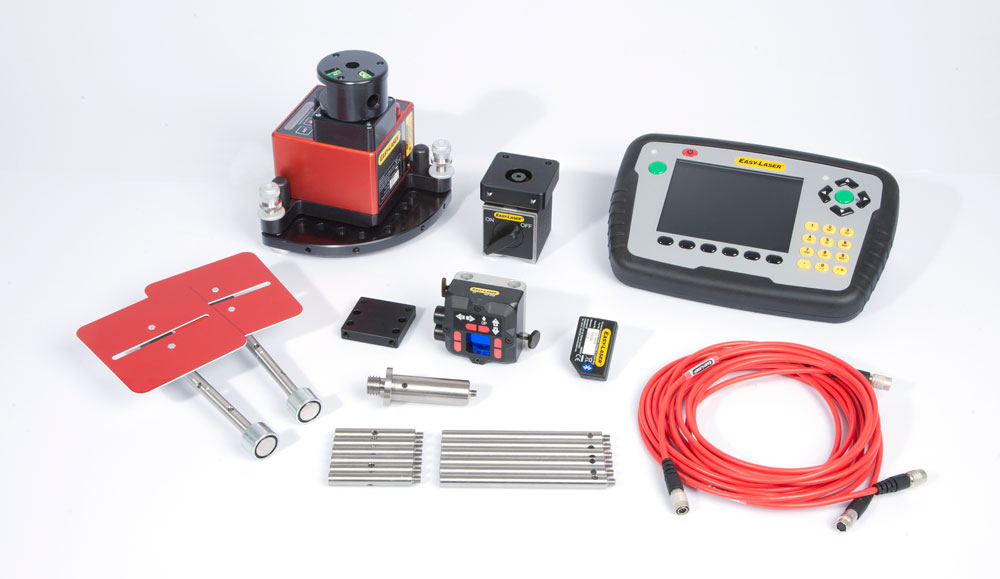
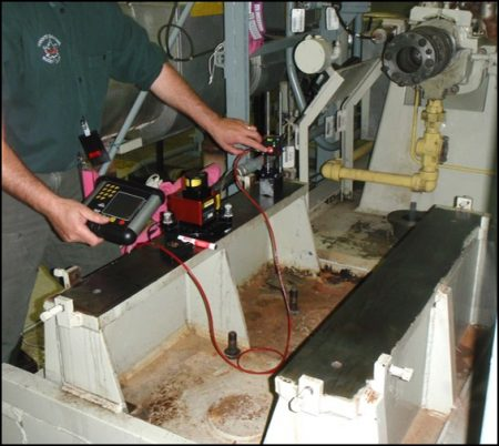 PHOTO (right) – Base flatness measurement with Easy-Laser alignment measurement system.
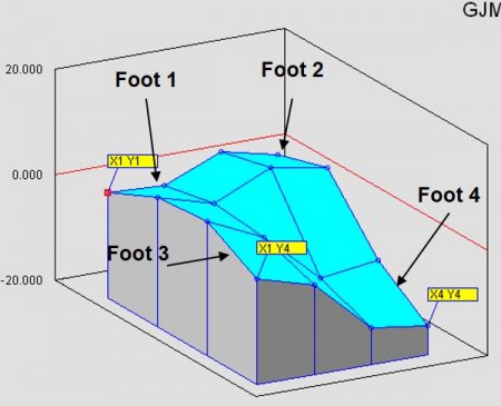 This is the full report you get and I have numbered the feet. I have also highlighted (in red ) the reference point and the highest and lowest measurements that were taken.
 X1 Y4 0.0
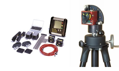
0 comments
Write a comment