


Tools of the Trade: Using the right condition monitoring tools doesn’t have to be hard
Many years ago, I worked as a shift mechanic in a large manufacturing plant. One of my duties was to conduct the shift walkaround. This entailed going to each section of the plant and examining equipment to see that it was in a safe working condition. This meant that if I went into the tank farm where we had a lot of chemical pumps, I would make sure that there were no leaks, no puddles on the floor, and no strange noises.
Another area of the plant was called the fan room, and in it were four high speed fans, the largest being five foot in diameter. They were an overhung fan design assembly, and the shaft was supported by two large pillow block bearings. The shaft would have been at least six inches in diameter. As a result of a serious breakdown in the past, we checked these fans by putting our hands on the bearings cover to see if it was running hot or not.
This was a very primitive way of checking, but it was many years ago, and not many plants had any measurement equipment, especially for temperature. Later, upon becoming a foreman in the same plant, I bought a temperature gun, so we could take a quantifiable measurement. This changed the shift walkaround. Now I could see a temperature range that the bearing would be in. We also used it for many more applications.
If you think about checked it with our hands, it was a little crazy, as one of these bearings exploded during an earlier breakdown. If you have ever seen a large high-speed fan wreck itself in a small, confined space, it is not pretty.
Buying a simple temperature gun now is a no brainer. The fact that it will give you a quantifiable measurement is invaluable. Why? Because to control a process you have to measure it. In maintenance, we have been proving that to be true. A simple temperature gun should be in every toolbox in the shop.
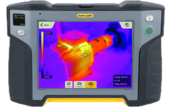
Figure 1
Still keeping it simple, Figure 1 is an Infrared image of a motor that is online (in operation). The image was taken by a display unit that is part of a laser shaft alignment system. It is a tool that tradespeople can use to take a simple temperature reading, but also can determine if thermal growth must be compensated for. They can use it as a before and after measurement that can be added to the report and history file. Yes, temperature measurements and how they are taken has changed a lot.
If I ask the question “When a tradesperson installs a pump and motor machine unit, how do they know if the work has been done correctly”? The common answer is that the alignment results from the laser shaft alignment system will indicate that the shafts are aligned (collinear). However, that’s only the shaft alignment portion of the installation.
You would also expect a detailed report on what was measured. Below is a list of what you should expect to be measured from the “AMERICAN NATIONAL STANDARD Shaft Alignment Methodology, Part 1: General Principles, Methods, Practices, and Tolerances,” and it states:
The final shaft orientations shall be documented as a permanent record. The documentation shall be in the report form and include recommendations as listed below. As alignment work may be conducted for new installation, as part of repair work, or during preventative maintenance work, not all, of these items are always applicable. All items that are measured shall be reported in addition to any items observed that may affect the machine operability or reliability.
- A description of the machine and its location.
- Date.
- Instruments and methods used for measurement.
- Person completing the task.
- Tolerance requirements.
- Offline to Running (OLTR) movement data.
- Base condition flatness and level
- Shaft and/or hub runouts.
- Machine, pipe, or conduit strain.
- Soft foot.
- The as-found shaft orientations.
- The as-left shaft orientations.
- The as-left axial spacing.
- Visual inspection (e.g., foundation and external connection items pipes, ducts, conduits, machine condition).
- A statement regarding compliance to this standard.
Whilst these are all important items as to what was measured, they do not give an assessment of the condition of the machine. For example, you can have a runout condition but still align the shaft. It is the same for pipe and casing stress, or a thermal growth condition. What these items or a combination of them will do is vibrate when the unit is operating. To assess that, you need another measurement device, and it can be a simple vibration meter (Figure 2).
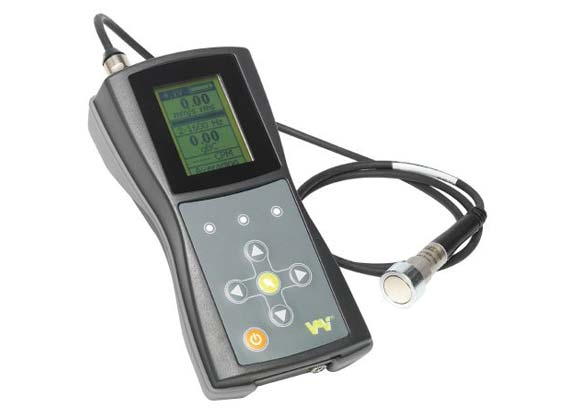
Figure 2 – Viber X3 Vibration Measurement tool
Vibration gives you the most information on a pump and motor unit. Many people back away from these meters because they do not understand the value, the result it shows. The most common unit of value in North America is a velocity reading measured as inches per second. You can look at it as the distance the amount the machine is moving over the time period of one second.
Simple measuring and monitoring of vibration can give your tradesperson a tool, so they know if the installation/alignment they just did is acceptable or not. This is a very powerful tool because it gets us on the path to why. Why is this machine vibrating more than its twin?
What he or she is measuring is a combination of items such as unbalance, misalignment, looseness, machinery structural strain, frame and foundations strain, and resonance. Most of these meters also give a bearing condition value and he/she can take readings in the axial, vertical, and horizontal planes, and compare these measurements to a known standard.
You can compare to the equipment manufacturer’s specification, the history record of the piece of equipment itself, or from another similar machine. These comparisons will give a good indication of the condition of the machine that you want to monitor. Then you can decide if any action must be taken.
When tradespeople have access to simple condition monitoring tools, they will find other uses for it. One of our customers uses their vibration meter to measure piping. If a pipe is not correctly supported, it can vibrate and effect the pump. A sort of “tail wagging the dog” scenario.
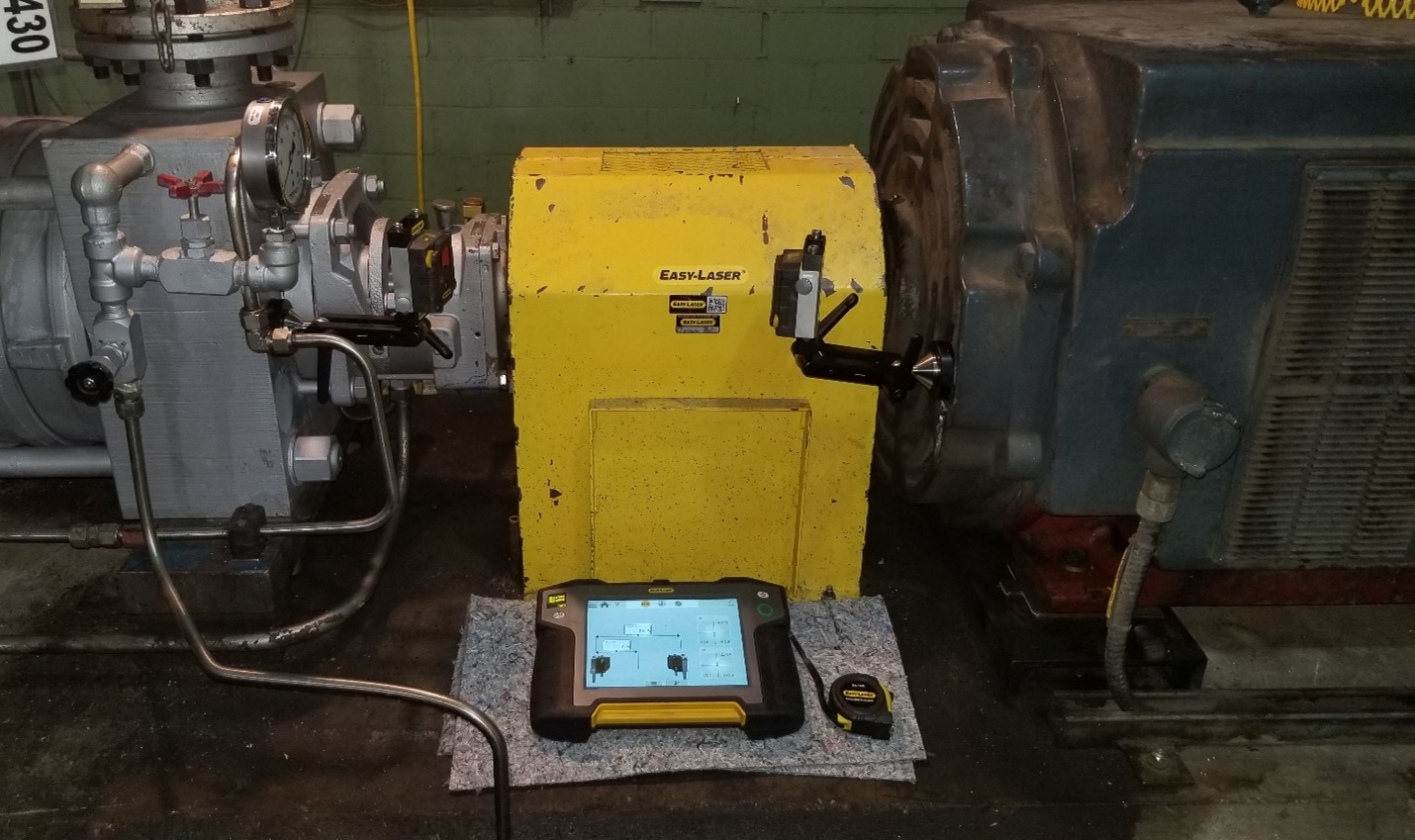
Figure 3
An often overlooked issue is thermal growth. The reason for this is it is not easy to measure without the correct equipment. When you measure thermal growth, it is the machine’s casing you need to measure. In figure 3, you can see two laser detectors on brackets that are mounted on the machines casing. They can be bolted or epoxied in place. It is best to have them close to the shafts center line as you can because what you are looking for is machine casing movement that affects the position of the shafts.
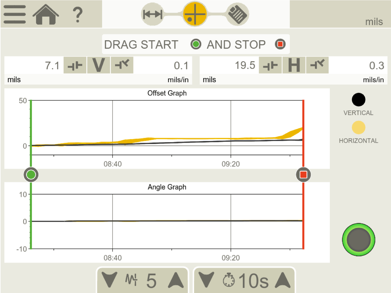
Figure 4 – EasyTrend Program from Easy-Laser XT770 alignment tool.
With an alignment tool, there is a live trend program (Figure 4) that will show the growth/movement when the machine reaches full operational temperature. The values you see are what you use as targets. These targets are input into the alignment program before you take the measurements to compensate for the machine movement. It is movement because yes, most machine will grow upward, but machines can move left to right and down. For example, the inlet of a large blower can shrink down.
When you give the right tools to tradespeople it does not take them long to find other uses for them. Many are using the EasyTrend program to measure the movement of the shafts as they bolt up the piping on a pump. They add this to the alignment report, which gets added to the machine’s history. This is what the gentlemen are doing in first featured image at the start of this article. You can see a post I wrote on this measurement here.
They do this because the new ANSI standard for shaft alignment states,
External forces from piping strain, flange strain, conduit strain, attached ductwork, etc., applied to machine cases subject to shaft alignment tolerances, shall not be sufficient to cause changes in the shaft alignment of magnitude greater than 50 micrometers (2 mils) vertical or horizontal measured at the coupling.
Is this something you measure?
The moral of the story is having the right tools is important. Knowing what to measure and the correct tolerance is crucial. That is why we call it precision maintenance.
You can also find a version of this article in MRO Magazine’s June 2020 Digital Edition here.
About Author

0 comments
Write a comment