

A Case Study on Why Pipe Strain Needs to be Measured
 Let us review this case study on a common issue when working on a pump and motor alignment done by Brian Franks, Owner and Field Service Technician of JetTech Mechanical (www.jettechmechanical.com).
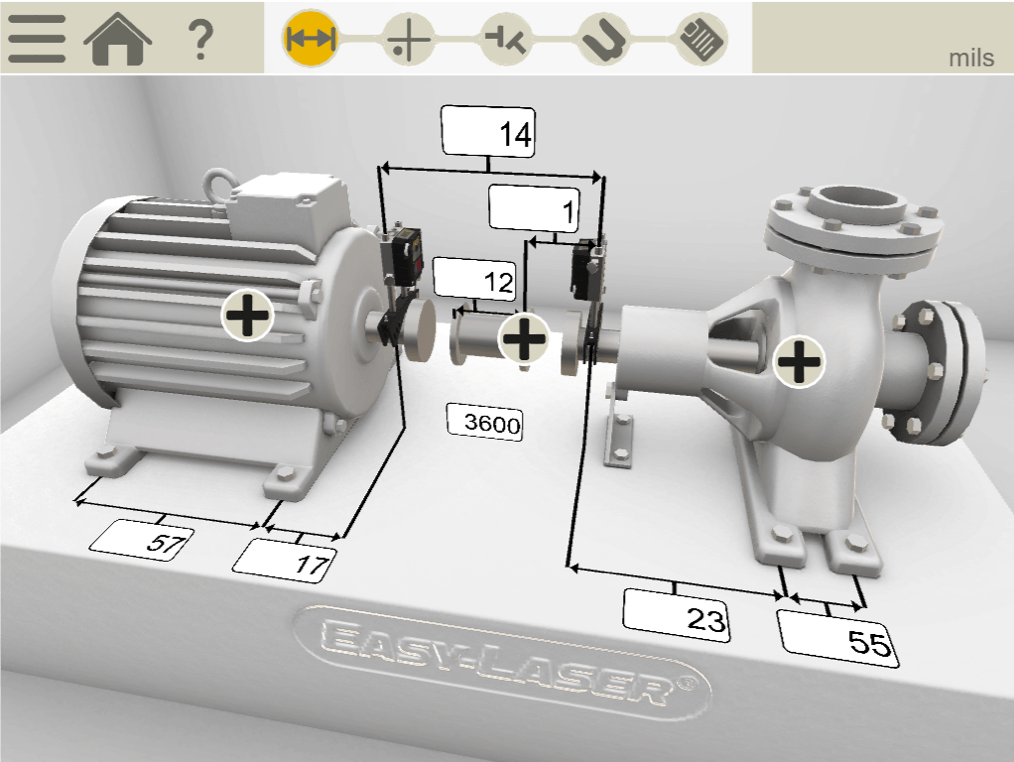
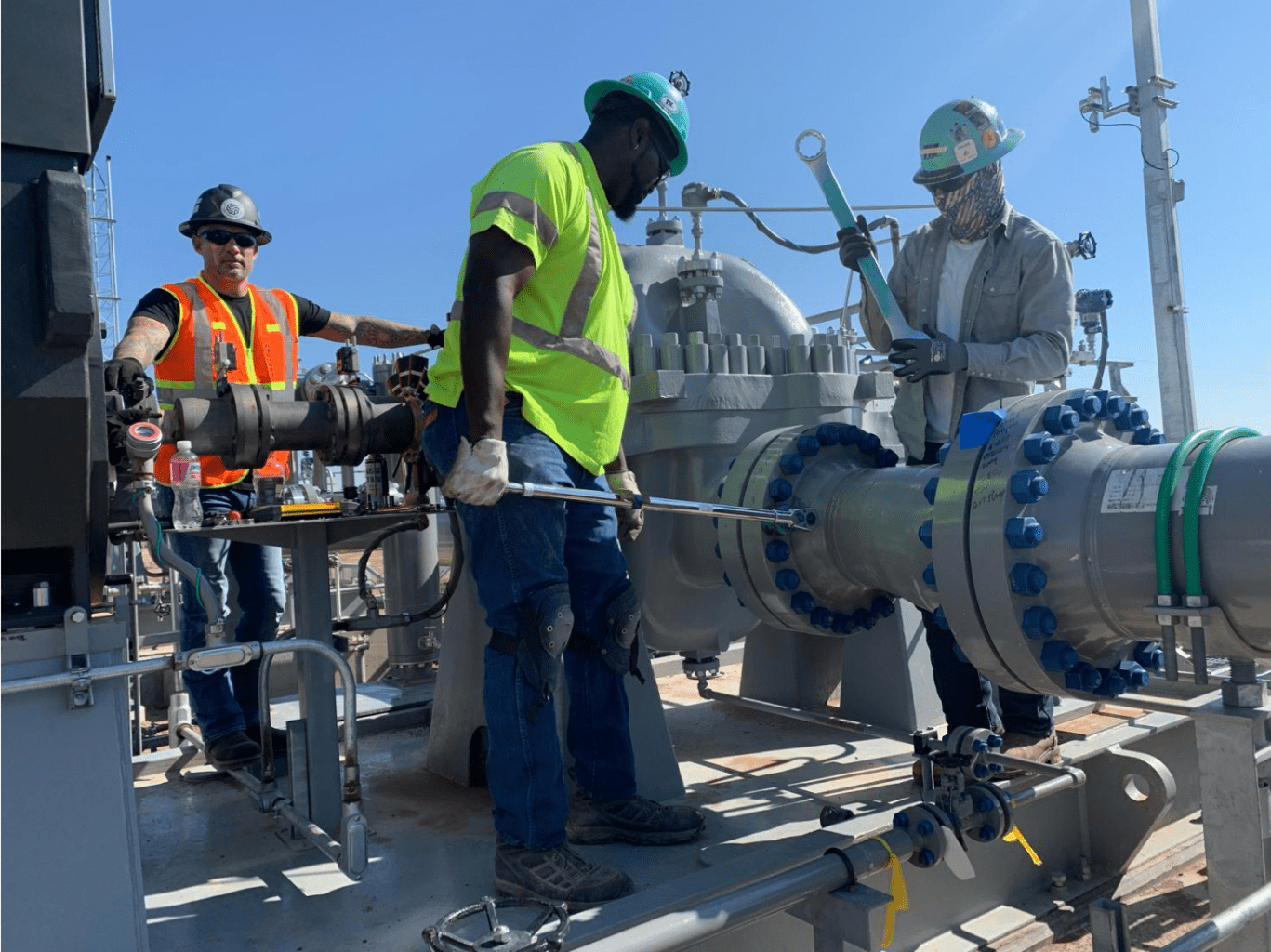
He begins in the normal manner entering the distances of the machine. As you can see this is not a small machine (see Figure 1 below) – there are 57 inches between the motor’s feet and if you add all the measurements together you have 87 inches from the Stationary laser detector unit and the back foot of the movable machine (motor). Notice also that it is a spacer coupling.
He continues doing the alignment work by taking a softfoot measurement on each of the machines and as you can see, there is very little, so we know it’s a stable base that the machine units are sitting on.
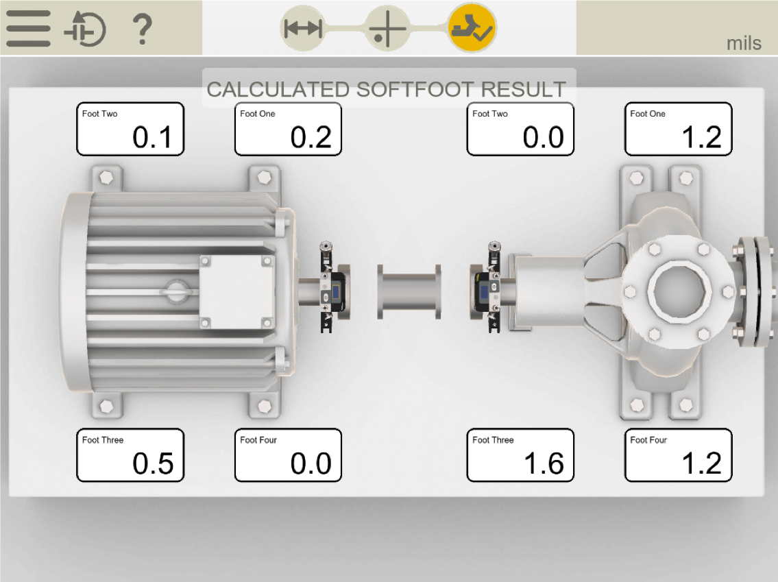
An important note is that they would need the coupling open/loose and the pipe disconnected in order to do this correctly.
The new ANSI standard (ANSI/ASA S2.75-2017/Part 1) allowable softfoot tolerance is two thousandths (0.002 thou or 2.0 mils) of shaft deflection and he is below this, so he is good to go. He documents it for his report.
He now performs the machines’ shaft to shaft alignment.
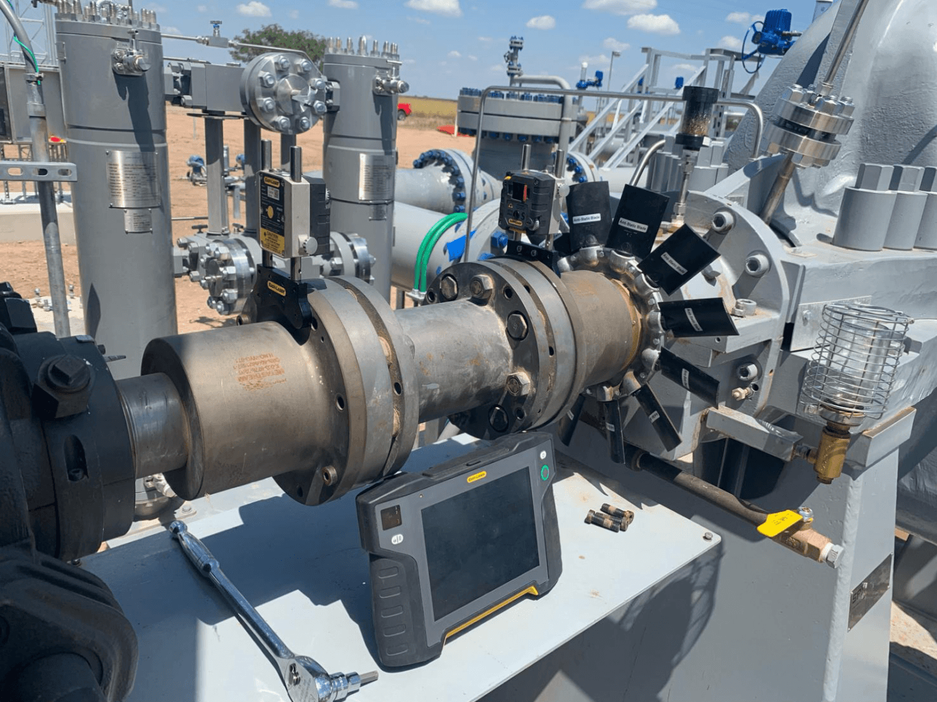
Notice that he’s removed most of the bolts from the coupling in order to allow the coupling to flex. This is a stiff coupling so you don’t want it locking up during the alignment and you also want to make as few moves as possible. So, this is a good practice. This also tells me they know what they are doing which is good.
The tool they are using is an Easy-Laser XT770 which is a dot laser system that can read in the horizontal and vertical plane.
Because this is a spacer coupling, it has two planes of flexure. This means that the measurement results will be two angles. It will say so many thou (or mils) per inch.
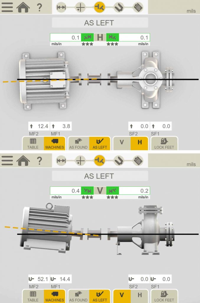 Take a look at these results. They are excellent. The top graphic is the horizontal plane because we are looking down upon the machines and we can see all four (4) feet of the movable machine, in this case the motor. The angle is only 0.1 of a thou or mil per inch at the first flex plane. And the angular is the same 0.1 of a thou/mil per inch at the second flex plane. Which is very, very little misalignment.
The lower graphic is vertical plane. We are now looking at the machines from the side. The results at the coupling are very good, we can see the motor has to go down 52.1 thou at the back end, however this is not that important because of the large distances between the machines feet. It also is a spacer coupling which means the angle at each flex plane are in tolerance.
What is important is the angle measured at both planes of flexure at the coupling. And in this case they are excellent!
The next stage is to attach the piping. Brian is looking for shaft deflection as the pipes are attached and torqued. He wants to add a pipe strain measurement to his report.
The crew will use a flange mounting and tightening procedure. This will take some time but the XT770 will operate 24 hours on batteries.
To do this he positions the laser/detector heads at 12 o’clock so that they are reading in the live mode in the vertical and horizontal planes.
He will then use the dynamic measurement program to record the results. In this program he can watch or monitor any change to his alignment results. He will flip the machines making the pump the moveable machine and make the coupling a single flex plane to give a more precise result.
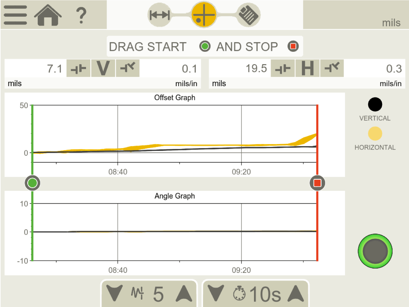 I find this quite interesting because as you can see the pipe has pulled the pump down by 7.1 thou/mils. The black line shows the moveable machine in the vertical plane and in this case we are moving and reading the stationary machine which is the pump.
The top part of the screen is showing the offset, while the lower displays the angle. As you can see, there is no angle or very, very little. The yellow line is showing the movement in the horizontal plane, and you can see that it’s been pulled over a whopping 19.5 mils! This puts it well out of tolerance.
In section 6.1.8 Pipe strain, conduit strain, duct strain, and other external forces of the ANSI/ASA S2.75-2017/Part 1 standard it says,
“External forces from piping strain, flange strain, conduit strain, attached ductwork, etc., applied to machine cases shall not be sufficient to cause changes in the shaft alignment of magnitude greater than 50 micrometers (2 mils) vertical or horizontal measured at the coupling.”
Obviously, some work needs to be done to correct these alignment results, but the bottom line is that this pipe strain has been measured and recorded. It’s a quantifiable value that will allow the crew to make a decision. That’s the kind of report I would like if I’m a customer or maintenance supervisor.
Well done JetTech and Brian Franks for doing the job right. Visit JetTech’s website here: https://jettechmechanical.com/.
About Author
I has been my experience when doing pipe strain on horizontally opposed suction and discharged on pedestal mounted equipment that you alternate between the suction and discharge.
You pull the center line horizontally as best you can to 3:00 9:00 alternating between the two lines until the piping is tightened.
This should be done before grout to assure you can line the equipment after it is set in stone or epoxy 🙂
API Spec on those flanges for parallelism back in the back would have probably been .010 thousandths.
The crush of the flexatallics would be worked in your favor.
I spent years and years in the field correcting that type of strain, I normally ended up doing most of the pipe stress relief on the equipment.