

Soft Product, Harsh Conditions
In my business of providing alignment services, I get to see and work in a lot of harsh environments. In the past, I have written about doing this work in cement plants, which I think are some of the toughest because not only does the cement dust plug up the machines, it’s so abrasive that it wears them out quickly. Recently, I calibrated a laser system that had been used for a long time in a coke plant at a steel mill and I was reminded of just how harsh and very dirty these facilities are. Another example is a plant that makes a nice soft product – but the environment is anything but – it’s a tissue mill. Can you imagine how much nice, soft tissue is used in North America per day? Per hour? Tons! It’s a large industry.
In one of the tissue plants I am working in currently, you could see some of the tissue or pulp floating in the air. It would get into every corner of the plant – including the machines. The motors would draw it in, adding a layer of insulation they did not need. Unseen components of this harsh environment are the chemicals used in the process. They attack the motors by adding a coating that degrades them – and all the machines over time.
The main machine in the plant we are working on now is called a Yankee Dryer. Imagine a large drum as big as a living room that is heated by steam and is spinning. The wet pulp is sprayed onto the drum as it rotates and the steam heat dries the pulp and creates the tissue. The operators can control the density (the thickness) of the tissue by adjusting the speed of the dryer. This dryer had a higher than normal vibration at different speeds, so Steve Cameron of Advanced Balancing had made the call that the drive shafts needed to be aligned. My company went in to support the alignment work.
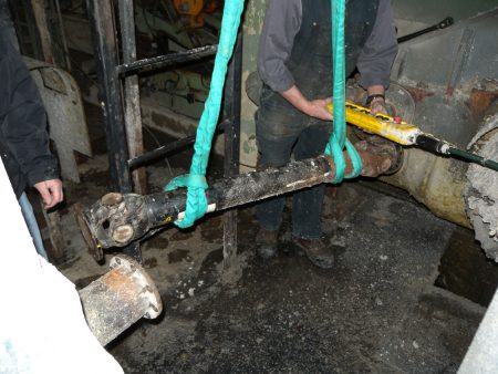 This Yankee Dryer was driven by two separate motors that drive a single gearbox, which in turn drives the dryer. The connecting drive shafts are universal jointed shafts (also known as Cardan shafts). The shafts are designed to compensate for offset misalignment. With offset, the shaft will run in an angled position (it will be slanted), but the shaft will compensate for the offset (up and down or left to right). However, the two connecting flange faces, one on the motor and the other on the gearbox, have to be parallel with each other in both the vertical and horizontal plane. Yes, they can be offset with each other, but if there is any angle involved, they will move in the axial plane and vibrate if running at speed. In essence, the shaft is opening and closing along its length as it rotates. These shafts have a splined slip assembly to compensate for this movement. It works at very low rpm (even so, it will still wear out), but at higher speeds it will vibrate and eventually damage the motor, shaft and gearbox. The solution is easy: align the flange faces. Most good laser systems provide Cardan (universal joint) shaft alignment programs. In this case, we used an Easy-Laser E710 with specially ground, flat, anodized aluminum mounting brackets. These brackets were attached to the flange faces because that’s what we were aligning – not the outer edge. This meant that we had to remove the shaft (PHOTO – left), which was worth doing if we wanted to get it right. The dimensions and distances were input into the system. The heads were rotated after each measurement was taken and then we read the results live on the device’s display. We made the vertical correction by shimming the moveable machine (in this case, the motor) at either the front or back feet. Then we adjusted horizontally at the front or back feet while watching the movement results live on the device’s screen. We only had to adjust the machines at one foot pairing because we were only correcting angular misalignment – not offset. The next day, after the shutdown was over and the Yankee Dryer had been restarted, there were some happy faces in the plant. Why? Because we had removed the high vibration level. This vibration had been restricting the speed of the dryer, so now that it was gone, the big bonus was that production could now speed up the process. This meant it has increased capacity and production output. In other words, the plant has more opportunity for more throughput, if it wants. This is a win-win scenario. The maintenance department increased the reliability of a machine unit and production added potential capacity.
One note of caution is to be observed when aligning universal jointed shafts. They are not designed to be perfectly in line. In fact, if they are aligned, they will damage the bearings in the joint. This is because they need a certain amount of misalignment to draw the lubricant through the bearing – the same way a gear coupling does. This happens more so in shafts that have needle rollers as opposed to the ball bearings used in many industrial applications — but don’t worry, as a small amount of offset will look after this. (If you have the need to have a shaft inline, you should be using a jack shaft.) There is also another winner – us. By doing the work correctly and working to the correct tolerances, we have achieved very good results that should prove to management that precision driven maintenance techniques should always be used.
About Author
0 comments
Write a comment