

Dowel Pins: Should we be using them for pinning general purpose machines?
Dowels have been used by carpenters for centuries. They would have a length of rod which they would cut the required amount needed from it. It would have been inserted into a joint to give the joint more strength and to stop or reduce the share of forces that are on that joint. Basically, a pin to keep something in the same position. It is not designed to be fastener or a clamp, as something else would meet this requirement. So it’s no surprise that we see them in our industry.
Now let’s not confuse these dowel pins with locations pins. Location pins are used to position one component with another. The auto industry uses them a lot. For instance, the gearbox to block, cylinder head to block and timing chain covers to block uses location pins. We use location pins on split casing pumps, gearboxes and compressor covers and in many more places. We use similar devices such as step fit or rabbet fit on a flanged motor. We have other examples however, they all do the same thing which is marrying one component with the other and insuring they are in the correct position.
 Dowel pins are different; they are used to lock/pin a machine in place after it has been positioned and aligned.
Figure 2 (left) – Dowel pin with thread, used to help for removal.
In some instances, I understand that on high speed/high torque machines such as large turbines they have to pin them down. They expect growth so they control the movement of the machine. One example that comes to mind is a turbine that is dowel pined at the front of the machine. This restricts the axial movement of the machine thus protecting the coupling. The back end is not pinned and allows the machine to grow along its length without restriction. It is an engineered design that works well for this application. This use of dowel pins makes sense to me.
However, on general purpose machines, I don’t like to see them used. I believe that just by using the correct grade and torque for the hold down bolts is adequate enough to keep the machine in place. And what’s more, many of the dowel pins that I see are incorrectly installed and are actually detrimental to the machines alignment.
Let me explain. We all know that a machine will move as it comes from offline to online reaching operating conditions. With this thermal growth, it will move axially (along its length) horizontally (side to side) and vertically (up or down).
We tend to focus on the vertical movement because as the machine heats and it wants/needs to expand down it cannot because the base restricts the movement. Instead, it moves up and creates misalignment between the two shafts and we compensate for this by shimming.
But what about horizontal movement? This is an interesting one as there are some machines that will move a large amount in the horizontal plane, such as reciprocating compressors, but this is known and should be compensated for.
We know that machines grow in the vertical plane so common sense should tell us that it will also grow in the horizontal. We don’t see too much movement horizontally when checking hot alignment. The reason I believe is that when machines expand outwards it is not restricted (by the base) so it can spread out equal amounts. I believe that there is also some movement between the motor feet and the base. I call it creep. Even if the bolts are torqued down I still think there is some movement or “creep” as the machine and the base grow or shrink. I know it’s possible to move a machine in the horizontal plane even after its tightened down as long as you apply the right amount of pressure with a good jacking bolt. And that’s what thermal growth is, it’s constant pressure. If the growth is equal amounts and there is no restriction, we don’t see as much movement. But what if it is restricted?
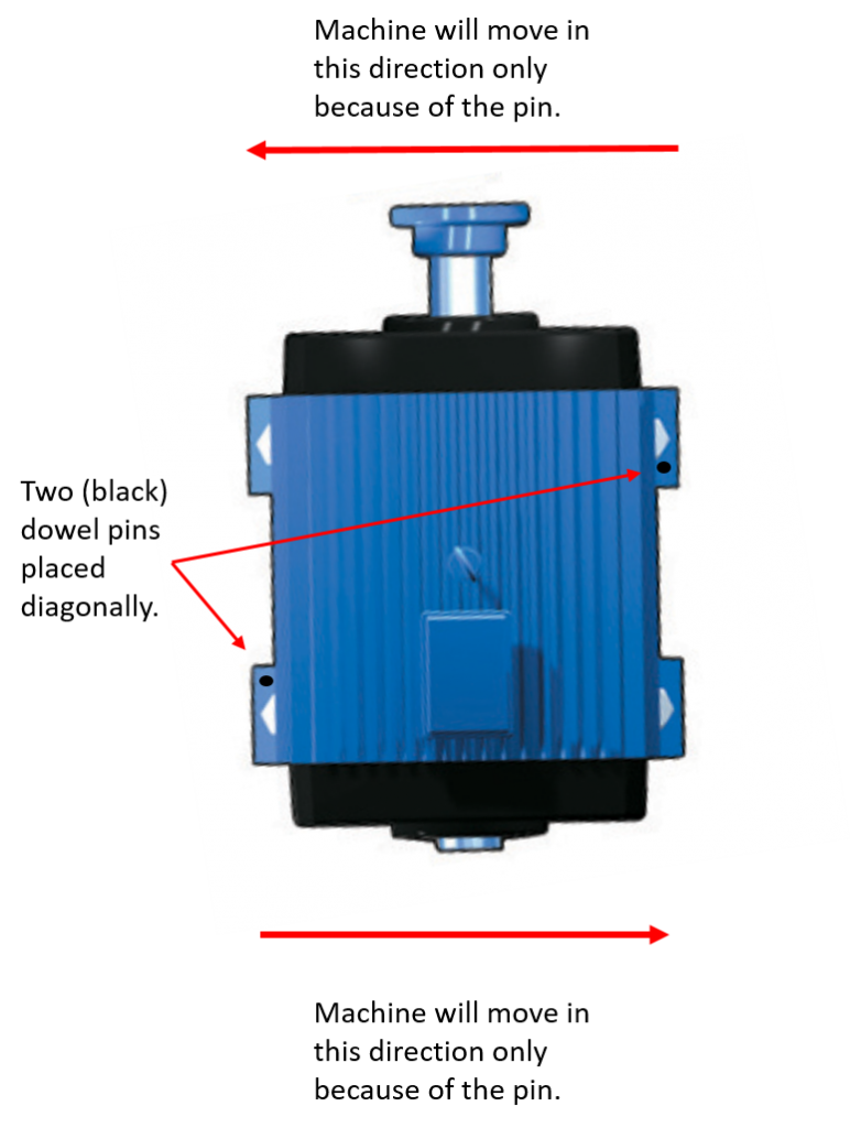
The graphic on the right shows two dowel pins installed diagonally. These pins will restrict movement in one direction only. When the machines grow and push against the pin, it will have to move in the opposite direction. This means that this machine will rotate in the horizontal plane as it reaches operating temperature thus, misaligning the machine at the coupling.
Figure 3 (right) – Bird’s eye view of a motor with potential horizontal movement due to dowel pin placement.
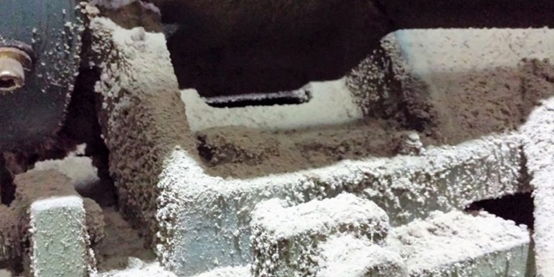
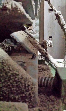
The machine that we removed these dowel pins from (Figure 4 below) was a large electric motor that was driving a gearbox which in turn was driving a roll. The dowels were installed diagonally as were the dowels in the gearbox. The gearbox dowels were the opposite to the motor so misalignment was compounded.
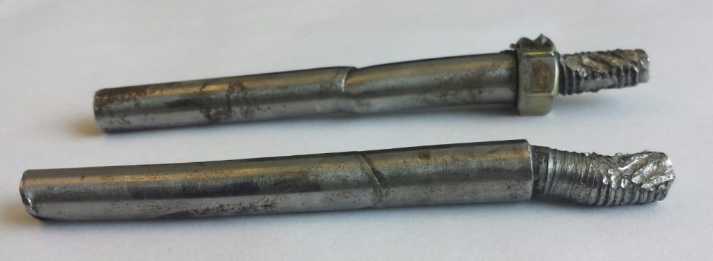
Figure 4 (above) – Dowel pins removed from a motor.
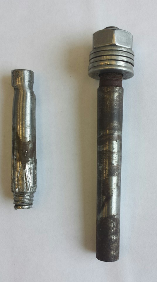
Figure 5 (left) – Two dowel pins removed from machines.
If you look at these two pins (Figure 4 above) you can see that there is a step (or indent) in one which to me means that there has been movement. The customer says that these machines have never been re-aligned since the original installation so I think the step has been caused by the thermal growth of the machine.
To remove these dowel pins can be a challenge. The simplest way is using a slide hammer (if the pin is threaded). You can make these up easily using a barrel nut, a length of threaded rod, a weight and a stop. They work very well as long as you have the room to get it in. If the area is obstructed, if there is a step in the pin or it’s bent, then the slide hammer does not work as well. That’s when the fun (and the wasted time) begins.
For example, I have seen the threaded end break off using a slide hammer. Then it was decided that they could punch it straight through not knowing that the pin was tapered. When that didn’t work they tried drilling it out which was taking a long time and not working. So eventually they pried the unit up and cut the pin with a Sawzall. This all takes time.
Have a look at these two pins (Figure 5 left). The first one (on the left) looks to have been cut short and you can see that it has not been installed deep enough because the step (where the joint will be) is very low to the bottom. You can also see that there was a lot of exposed pin at the top. The step is because someone moved the machine after it was pinned. However, that’s just a guess because no one is saying anything when we ask.
If you look at the next pin (on the right) you will see that its discolored. The reason for this I think is that it’s not making good contact with the sides on the tapered hole so that air can get in and the pin gets oxidized (discolored). This pin came out easily so that means it was probably loose.
The bottom line is that you have to install these pins correctly otherwise it’s a waste of time. And that begs the question of why they are being installed in the first place? If the reason is because of known circumstances such as to restrict movement of a machine in a certain direction, due to thermal growth movement, then it’s a good valid reason. In other words, there has been thought going into the decision. But if they are pinning the feet because someone thinks it would be a good idea and they have seen it somewhere else then I think you should review this “good idea.”
Now I admit that I haven’t done a lot of research or experimentation into this subject. My conclusions are based on many years of experience and my observations. This article was written in the form of a question. I have given you my opinion, so what’s yours? Do you have anything you can share? If so I would like to hear it from you and if appropriate, we can share it in our next newsletter.
About Author
Good post; my understanding exactly. Some people have tried to pull the pins, make small alignment adjustments and then put the pins back without re reaming the holes – disaster! I say if you see pins, investigate the reason for them and if they are not necessary, chuck them.
Totally agree. I see in my industry (high-tech) an extreme overuse of dowel pins for basically everything.
They key here is that, as the author says, the pin should work AFTER the assembly is done, not acting as an enabler for an assembly step.
This is usually not the best way to use a high-precision alignment, by the way. Pins should be used for what they are for.