

Are you using coupling tolerances to align your machines? You’re doing it wrong.
If we want to get into precision maintenance, we need to be aware of the differences between shaft alignment tolerances and coupling tolerances.
I just recently read an article from an online Reliability Maintenance website. Its from a well-known organization who sells training for Reliability Centered Maintenance and Condition Based Maintenance programs. The title read:
“The precision maintenance revolution brings world class reliability performance to your machinery and mechanical plants and equipment.”
Although the sentence isn’t very well written, it’s a good article that explains what precision maintenance is.
Is there a precision maintenance revolution? Or is it something that is just driven by marketing. Precision maintenance isn’t new, it’s been in our company name for many years. The PDM in BENCHMARK PDM stands for precision driven maintenance. Apparently, the term precision maintenance was first used by some actual rocket scientists who worked for NASA in the sixties. I first heard the term from Ralph Buscarello of Update international who is the gentleman that taught me shaft alignment using dial indicators almost 40 years ago. So, what is precision maintenance? If you look at precision in the dictionary, we are told it is:
1.The state or quality of being precise; exactness.
2.The ability of a measurement to be consistently reproduced.
The two key words for me is exactness and reproduced. As we know, a carpenter measures twice before cutting once. If the measurements are not the same (reproduced), he does not cut until he answers the question why?
Exactness makes statements such as “that’s close enough” redundant because we do not want “close”, we want it to be within tolerance.
That to me is how I define precision maintenance. It’s simply working to a tolerance. The reason we must work to an accepted tolerance range and not to an “exactness” is because in an environment such as rotating machinery, machines and mechanical parts are constantly subjugated to constant forces in which an exact measurement can’t be fulfilled. The problem is some people get confused by some of the tolerances that are out there in our maintenance world – especially when it comes to shaft alignment and the major mechanical parts involved.
Couplings
In rotating machines, the power transfer from the driver machine to the driven machine is done through a coupling. These are amazing mechanical components that must endure high stress levels from horsepower, torque, process load demands, etc.
Most of the couplings that are used for example, in a motor to pump setup, are flexible couplings. As the name implies, they flex – allowing for small amounts of misalignment. The amount of misalignment that they can tolerate depends on the design of the coupling.
There are a lot of different styles of flexible couplings including gear, jaw, grid, chain and disc couplings just to name a few. Each have their benefits and some work better in different applications. For smaller pumps, we normally see elastomeric couplings – like this jaw coupling below in figure 1. These are popular because you can always quickly open them up to do an alignment or replace the elastomer.
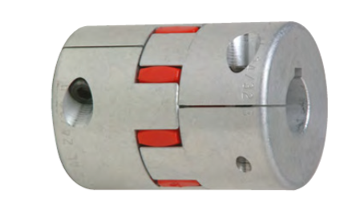
Figure 1 – Lovejoy GS Series Curved Jaw coupling
For larger pumping systems we see gear couplings (figure 2 below), but regardless of the style, they are all flexible (to a point) couplings. Couplings are one of the biggest work horses in the Power Transmission Industry.
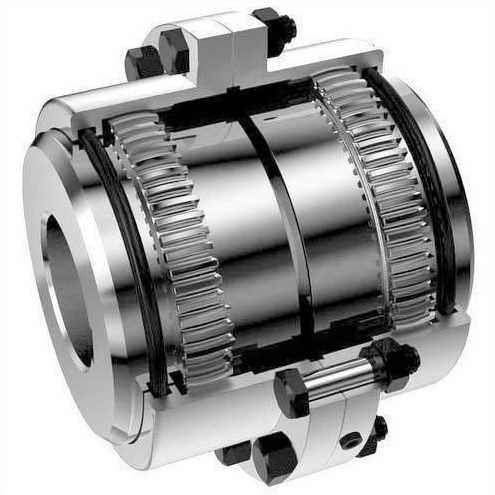
Figure 2 – Lovejoy HercuFlex Gear coupling
When we measure shaft misalignment, we must consider both types of misalignment: the offset, also known as parallel offset, between the two centerlines of the shafts and the angle between the two shaft centerlines (illustrated in figure 3 below).
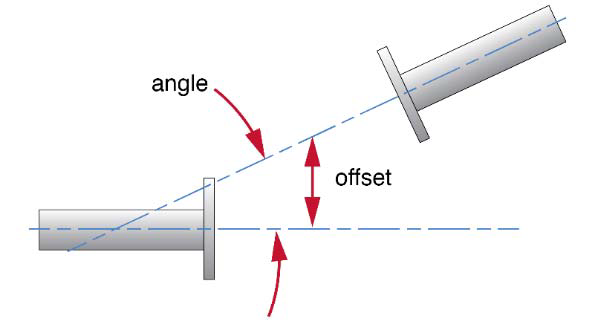
Figure 3 – Offset and Angular Misalignment
This means when you see a tolerance chart or table, you will see offset and angular values. And it is the same with couplings, they will give you a tolerance for both offset and an angle.
Coupling Tolerances vs. ANSI Tolerances
The Lovejoy S-Flex coupling (not shown) is also a short flex coupling and the offset and angle are given in their misalignment capability guide for each coupling:
Parallel, the S-flex Endurance coupling accepts up to .062 inches of parallel misalignment.
Angular, the S-Flex Endurance coupling accepts angular misalignment up to 1 degree.
In this instance the angle has been given as a degree. We can easily convert that to thousands of an inch (thou), per inch. One (1) degree is 0.01745” (thou) per inch. That means on a two (2) inch coupling you would be allowed a gap at the top or bottom and side to side of 0.035” thou.
Below (figure 4) is a shaft alignment tolerance chart from the American National Standard (ANSI) Shaft Alignment Methodology. Part one – General Principles Methods Practices and Tolerances. If you look at the statement above the table, you will see that the RPM is the deciding factor in shaft to shaft tolerances. The faster the machine runs, the tighter the tolerance.
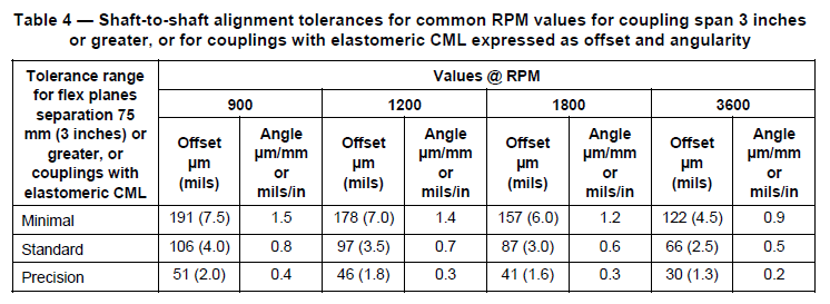
Figure 4 – ANSI Shaft Alignment Tolerances for short-flex couplings.
If you look at the tolerances, you will see it written in metric and imperial. In the brackets, the tolerance is in mils. A mil in the same as a thou (thousand of an inch), its just written differently. One mil equals one thou ie. 1.0 mil = 0.001 inch (thou). Mils are used throughout North America, although mainly in the USA and this is an ANSI Standard.
If we look at the table under 1800 RPM, which is the most common RPM in industry, it shows the allowable tolerances divided into three ranges:
Minimal – 6.0 mils of offset and 1.2 mils per inch of angle.
Standard – 3.0 mils of offset and 0.6 mils per inch of angle.
Precision – 1.6 mils of offset and 0.3 mils per inch of angle.
When comparing the minimal ANSI tolerances to the tolerances of the jaw coupling in thou.
The coupling tolerance is:
0.062” of offset, 0.01745” per inch of angle.
The ANSI standard is:
0.006” offset, 0.0012” per inch of angle.
Why the big difference? The coupling manufacturer is not trying to mislead you, they are simply pointing out that their coupling can withstand a high degree of misalignment which is a great benefit to you, the user. The fact that the bearings in the machines cannot handle the high vibration created from too much misalignment is not their concern. It’s yours.
And the reason it’s a benefit to you is that many machines have to be offset, or misaligned if you like, when installed so that they can expand into alignment when at operating temperature (thermal growth).
This means you need a coupling that can handle large amounts of misalignment.
So, with that said, it is important to know that the specification sheet you get with your coupling is for the couplings, not for shaft to shaft alignment tolerances.
Beware! While most coupling manufacturers give good information, some do seem to be on the outrageous side. I have seen one that claims an offset of 1/8 of an inch and four (4) degrees of angle! Even if it has a rubber tire for an insert, it will have very high vibration levels that would destroy the bearing, seals and eventually the machines that they are attached to.
Open-Coupling Alignment
Let me leave you with one last item to think about. During our alignment training we spend a lot of time on couplings because they have a large influence on alignment work. One of the most common questions I get asked is “should the coupling be loose or open when we align them?” Couplings that are installed (coupled together) when the machine is misaligned can lock up and not flex when the shafts are rotated. This can give incorrect results when aligning with a dial indicator or laser system.
We actually promote open coupling (disengaged) alignment so that we remove any potential strain from the coupling. This is because some couplings are quite stiff and will deflect the shafts.
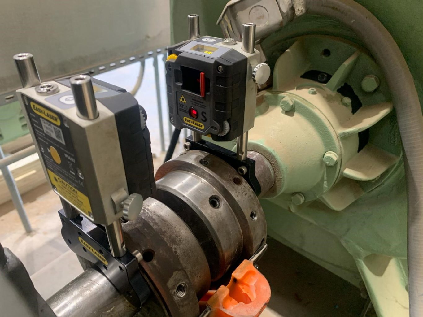
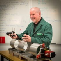
Figure 5 – Technician from JetTech Mechanical (https://jettechmechanical.com/) performing a shaft alignment using an Easy-Laser XT770.
Figure 5 shows a blower that is being aligned. The man that’s doing the job is only using half the coupling elastomeric link to reduce the shaft deflection. It’s a good coupling and this was his solution to avoiding potential coupling interference. What would your solution be to get around coupling stress when doing shaft alignment?
The bottom line for me is that I’m ok with precision maintenance being the new revolution, but if you plan on joining, make sure you get the right tolerances for your machines and follow the correct alignment procedures.
You can also find a version of this article in MRO Magazine’s June 2020 Digital Edition here.
About Author
0 comments
Write a comment