Understanding Thermal Growth in Your Rotating Machinery – Part 2
In the first part of this article (click here for Understanding Thermal Growth in Your Rotating Machinery – Part 1), we defined what thermal growth in machines is. We used an example of a machine growing equal amounts in the vertical direction. The fix was to lift or lower the machine of choice by a total of 5 thou (0.005“) to compensate for the growth offset. To reiterate this example a little further see below the temperature readings we took on a motor running at approx. 1800 rpm. The first reading (PHOTO – below) the front foot is 51° C and the next reading (PHOTO – below) the back foot is 38° C.
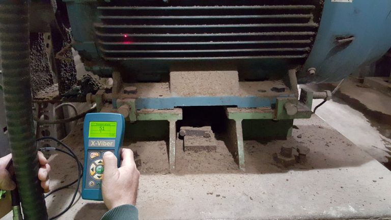
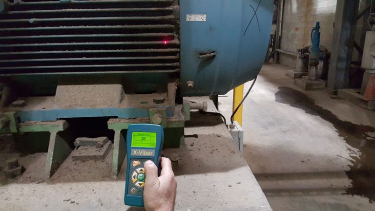
To calculate the growth based on the temperature in the picture we need to know three things and multiply them: the change in Temperature (T), the length of material we are measuring (L) and the coefficient of thermal expansion of the material (C). For more information on why these three things, go to Part 1 of this article.
To find the temperature change, we first transform from Celsius to Fahrenheit so that we can use the same formula we started with in Part 1 of this article. 51° C becomes approx. 124° F and 38° C becomes approx. 100° F. Next, we take away the ambient temperature, which we know is 73° F. This gives us a temperature change of 51° F (124° F – 73° F = 51° F) at the front foot and 27° F (100° F – 73° F = 27° F) at the back foot – both of which are small amounts.
The length (height) of the section we are measuring – from the foot bolt to the centre of the shaft is 12 inches.
It is important we know what the material we are working with is. In this case, it is mild steel. The coefficient of mild steel is 0.0000063 (inch/° F).
We then plug our numbers into the Thermal Growth formula for each foot starting with the front foot (FF):
FF = T x L x C
= 51° F x 12” x 0.0000063 (“/° F)
= 0.003” (3 thou)
We do the same for the back foot (BF) and we get 0.002” (2 thou) which is not a lot.
A 0.001” (1 thou) difference across the distance between the feet is not an issue at all. The 0.003” (3 thou) in growth at the front feet could be an issue if the motor was running at high speed, but it is not, so we are good to go.
Machines can move and grow in equal amounts as we have just seen in this example, but more commonly, they move in unequal amounts. This can be more of a concern because now we are adding angle to the offset. So let’s look at what angle can do to the machines alignment.
How Machines Grow in Unequal Amounts
There are other issues that make machines move. For instance, the sheer torque at start up from the driver (ie. motor) to the driven machine, if either machine is not secured properly or the base is inadequate or flexible, can result in one or both of the machines to move. Even the power/force of liquids or air being forced though piping or duct work can make machines move – especially at start up. More often than not however, it’s because of temperature changes from ambient temperature when off line to operating temperature when online (running) – known as Offline To Running (OLTR or OL2R).
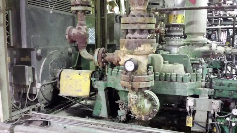
(PHOTO – Above) If you see paint blistering on pipe work, it’s more than likely because the product is very hot.
Now remember, machines may not always move (grow) in equal amounts so when considering if thermal growth is an issue for you, you have to be aware of different temperature readings from the machines you are working on. Have a good look at the machines you are working with. Think of an electric motor. Many may have a cooling fan at the outboard end but nothing at the inboard end. Does that mean its cooler on the outboard end? Also, the inboard end is where the transfer of torque occurs at the coupling and there may be some heat transfer from the machine that’s being driven. Does this mean the inboard end will run hotter?
Recently a customer who works in the mechanical reliability group of his company asked me to have a look at some results from an alignment job. He had gone over it numerous times and confirmed that the numbers were in fact correct. However, he wanted us to review it and give an explanation of the corrections at the machines feet so he could pass it on to his technicians. He writes:
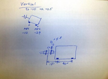 Our technicians recently did an alignment on a motor and centrifugal air compressor. They were using an E420 laser alignment unit and got results of -1.0 thou offset and -0.5 thou/inch angular in the vertical plane. The display was saying that the motors feet corrections were -10 thou low in the front and -29 thou low in the rear. Could you please take a look at these numbers and let me know if they make sense to you? Also, if the final values are within tolerance, why does the alignment instrument show corrections? Are they just to show us what we’d have to do to get the final values to zero?
He had included a photo of a basic diagram in his e-mail which is great because I’m a visual type person and like to see the problem. It had the misalignment at the coupling values (offset & angle), the feet corrections and the laser units and machines feet distances.
Well the answer is quite simple: we measure misalignment at the centre of the coupling and make the corrections at the machines feet. If you look at his picture diagram of the motor, the corrections at the feet are negative numbers meaning the motor is sitting low – so they have to add shim. Do they need to do a correction? No, the important numbers – which are the results at the coupling – are good. -1 thou (0.001“) of offset and -0.5 thou (0.0005“) per inch of angle is very good for this RPM.
If we constructed a graph based on the information given including distance between machine feet and the distance between the centre of the coupling to the front feet, we can then verify the results and his assessment of the alignment. The graph is to scale with the distance between each light blue line representing 2 inches and the distance between the heavy blue lines representing 10 inches – both going across the graph horizontally. In the vertical axis we have the distance between each light blue line representing 2 thou (0.002”) and the distance between the heavy blue lines representing 10 thou (0.010”). We can see that the projected centerline of the motors rotating shaft is in fact -1 thou low. And we can also see the angle is -0.5 thou per inch (see graph below).
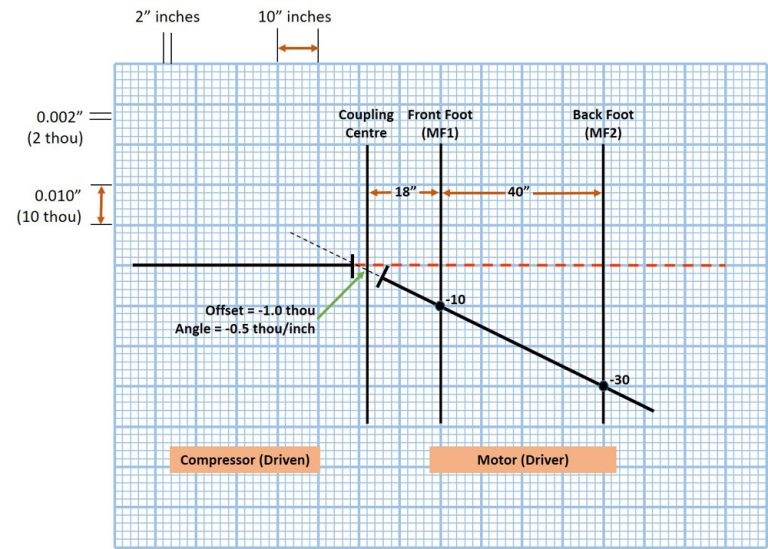
It’s the angle, although small at the coupling, measured over a large distance that leaves a large number still at the foot. Under normal circumstances you do not have to correct this. However, this is where the plot thickens as they say.
It should be said that all the above is all based on measurement taken when the machine is down and at an offline temperature. It turns out that when they had started the machine, which did start well, after a few hours the vibration levels increased so they shut it down correctly suspecting thermal growth.
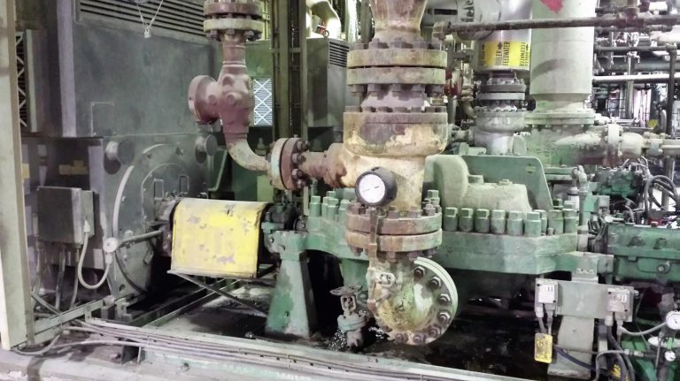
The compressor (Compr) runs at 150° F with the normal (ambient) temperature of 70° F – a difference of 80° F. This change in temperature (T) is multiplied by the length (L) from the foot bolt to the centre of the shaft – 25.5 inches – and then by the coefficient of mild steel, which is 0.0000063 (inch/° F). This works out to a thermal growth of 0.0128” – almost 13 thou.
Compr = T x L x C
= 80° F x 25.5” x 0.0000063 (“/° F)
= 0.0128” (13 thou)
Once we know what the growth is the rest is easy. We simply make the corrections based on the projected position of the shaft which we can draw. Based on this, you may think you just have to add 13 thou to the driver (motor) so that when the driven (compressor) machine heats up, everything will be aligned and in many cases that is true.
However, the plot thickens again with the reliability group doing some more investigating. They found that there is a cooling system on the back of the compressor with an operating temperature of 70° F. In fact, you can put your hand on the back end and keep it there but you cannot do this at the front. This means it will grow at an angle.
To see this visually, on our graph (below) we add the distance from the centre of the coupling to the compressors front foot (16 inches) and the distance between the machines feet (49 inches). We can drop in the lines which represent the planes of the feet and plot the point 13 thou high as the growth is positive. We then place the shaft over the plotted points of the compressor and we can now see the projected position of the shaft when it’s in operation. You can also see that there is a lot of misalignment when it is running.
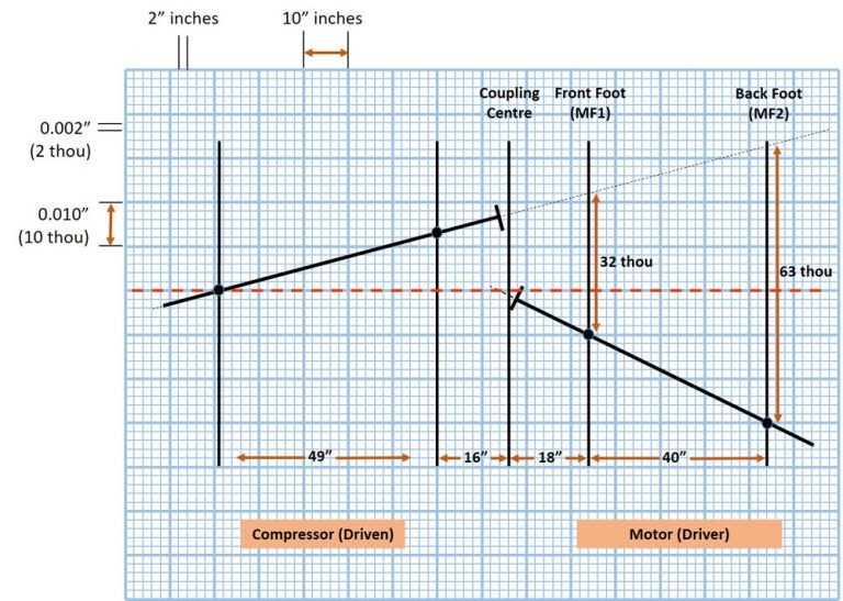
The goal is to have the machines shaft in line at operating temperature. As you can see, one way to do this is to add 32 thou to the motor front foot and 63 thou to the back.
So although the customers’ initial results were in tolerance for offline temperatures, the direction was pointing up which was the complete opposite of what it should be when you factor in the thermal growth of the compressor. It needs to be high and pointing down as you can see in the graph.
We measure thermal growth in the planes of the machines feet – from the base to the centre of the shaft (as depicted by the yellow arrows in the image below). If they are both the same the fix is quite simple; we simply lift or lower the chosen machine by the calculated amount. However, this is not always the case as machines grow at different amounts. If the outboard is hotter than the inboard, the shaft centre will be pointing down. If the inboard is hotter than the outboard, the shaft is pointing up.

This is important to know as even a small amount of angle can prove to be a big issue over a larger distance. Before you start your alignment work you need to know how much thermal growth is expected and in which direction. Look out for Part 3 of this article where we wrap up Understanding Thermal Growth.
For Part 3 of this article, click here.
About Author


0 comments
Write a comment