

Case Study: Bore Alignment on a Split-Casing Pump
We recently had a request from a customer to do some pump alignment. When we normally think about pump alignment, we usually think of shaft to shaft alignment. In this case, they wanted bore alignment. They were installing a brand-new pump and when they rotated the shaft, they could hear grinding.
After further inspection one of the techs could see that the bearing housing had been moved – either during shipment or when it was stored. They could see that the dowel pin had been damaged.
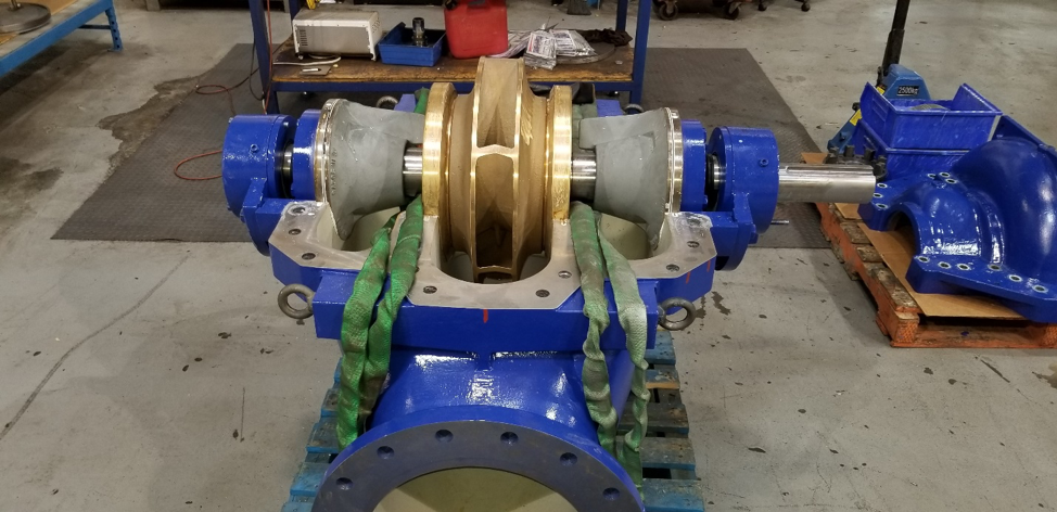
Figure 1
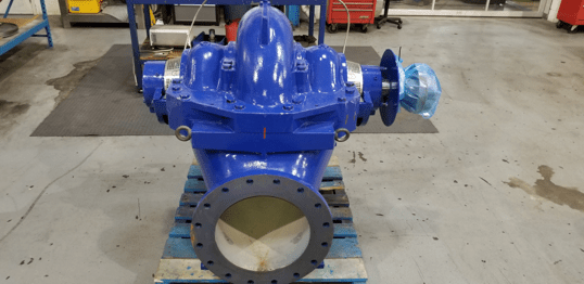
If you pop the lid off this style of pump (See Figure 1 – photo courtesy of KSB Pumps Canada), we see the shaft and the center mounted impeller. On each side of the impeller we have the wear rings, which sit in the bores. Outside of that we have two stuffing boxes or seal bores and outside of these we have the bearing Journals which are also bores. All of these bore centers need to be colinear, meaning in a straight line.
The old traditional methods for doing this type of work was done using piano wire or a mandrel. They would use the stuffing box or the wearing bores as reference points then measure to see if the bearing bores where in alignment. This method was “hit and miss” because its so difficult to set up and measure in this way. It also took a very long time.
Bore Alignment with Lasers
Using a laser-based measurement system has significantly reduced the time taken to do bore alignment. More importantly, it has improved the accuracy significantly. There are now automatic reports that go with the final bore alignment that has been completed – a documented history of the work is very important.
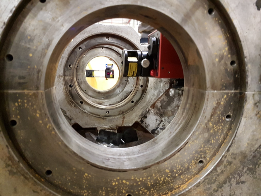
Figure 2
There are many different applications where bore alignment is done using lasers. For example, extruder barrels that need to be aligned to a gearbox in the plastic industry, crankshaft bearing journal bores in diesel/natural gas engines or compressors in the oil & gas and energy industries and stern tube alignment in the shipping industry. These are just three examples that show how varied the type of alignment work is.
Reference Points
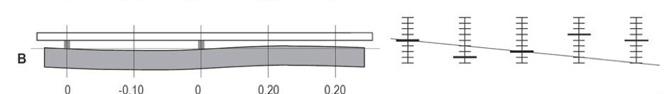
Before we begin let us review the meaning of reference points. The goal is to have the center point of each bore to be colinear, in the same line. Why? Because this will be the same line as the rotational center line of the shaft. So, in essence, we’re measuring straightness. In order to do this, we need two reference points.
Let’s say you wanted to measure the straightness of a rail. To do this you could use a straight edge and gauge blocks. You normally place the gauge blocks at either end of the object that you want to measure, and the straight edge goes on top as pictured in example A below. Then using the feeler gauge or a dial indicator you would measure along the rail so that it fills any potential gaps. The size of the gauge block (which is a known size) is subtracted and what’s left is the deviation. In this case, the reference points are the gauge blocks and it is important to know that they can be positioned anywhere at any point along the rail.
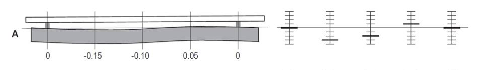
If you look at example B, you can see that the gauge blocks are at different positions along the rail and it gives us different results. Being able to position the two gauge blocks anywhere along the rail is a great benefit to us because we can decide the optimal position for adjustment of the rail. We could change the position of the reference points so that all values are negative numbers or change them so all the values are positive – whatever gives us the optimal adjustment/fix.
Having the ability to quickly change the reference points when using a laser speeds up the measurement process. It also gives us more options.
Bore Alignment on a Split Casing Pump
Back to our split casing pump application. The removable bearing journal housing in the photo below is actually bolted to the pumps casing. While waiting for the top cover to be replaced we can mount the laser. The Easy-Laser E950 Bore Alignment system was used for this application.
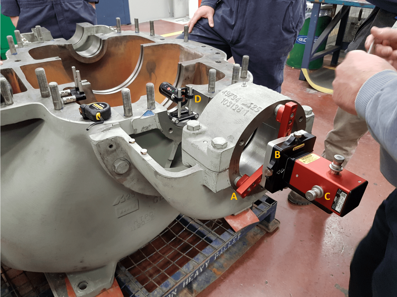
Figure 3 – A- The three magnetic mounting legs are adjustable to accommodate different bore sizes. B – The laser beam is adjusted for offset with four (4) screws on the hub. C – To adjust the laser beam for angle there is one screw for the horizontal and one for the vertical. D – The detector is attached to the magnetic bracket and sits in the stuffing box.
The D75 laser is mounted on a hub that has 3 legs supporting it and uses magnets to attach itself to the flange face. The laser beam can be adjusted in the offset and angle using the adjustment screws. This makes roughing in very simple.

Figure 4
Now that the cover is on (see Figure 4) we can adjust the detector to the center of the bore with just a measuring tape. We do this by sliding the detector up/down on the rods. Then we adjust the laser beam so that it hits the center of the detector. This is to make sure the laser will hit the detector at the farthest point.
The detector you see is mounted on a specialized bore bracket. It has four magnetic feet so that it can be rotated around the bore using the built-in electronic inclinometers for exact positioning.
Next, we position the detector close to the beam (see Figure 5, left) and adjust the beam to the center of the detector target using the hubs offset adjustment.
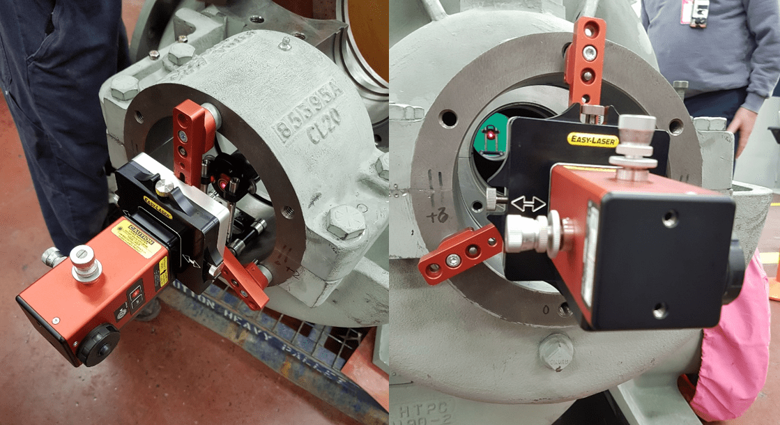
Figure 5
Then we place the detector to the far point (see Figure 5, right) and adjust the beam for angle. To do this electronically, we simply push the button zero (0) (in the Values program on our handheld display unit shown in Figure 6) when the detector is close and adjust the laser beam to zero when the detector is in the far position. This is all the roughing in it needs and it may take 10 minutes. Now we are ready to measure!
The plan for this bore alignment is to use the stuffing boxes as reference points. These are machined surfaces or bores that are part of the pumps casing and cannot be adjusted. We will use these points to compare the values we take in the bearing journals. We intend to take a total of 6 measurements, 2 in each of the bearing housings and one each for the stuffing boxes. The reason why we take 2 in the bearing journals is so we can see if there is any angular misalignment. We measure at six positions – two each for the main bearing and one each for the stuffing box that we plan on using as a reference point.
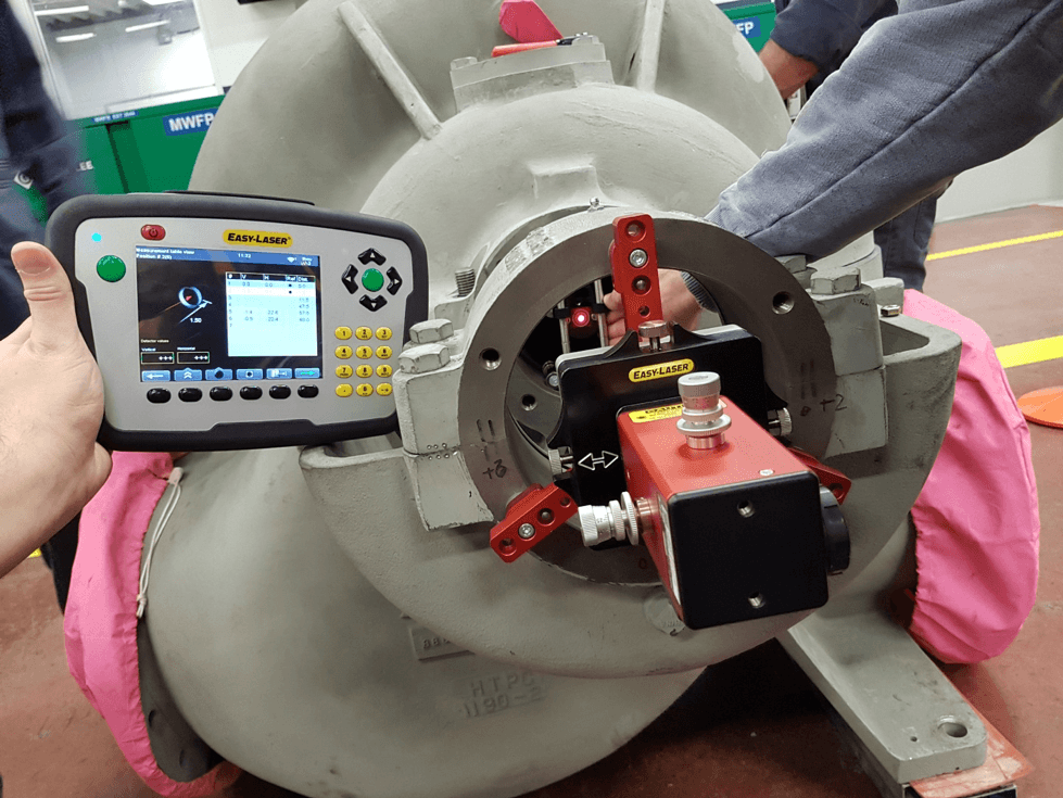
Figure 6
We rotate the detector inside the bores and take measurements at 12, 3, 6 and 9 o’clock positions. Rotating the detector gives us the center of the bore. This is a great advantage for us as you cannot do this with older traditional methods.
The diameter of the bores on the main bearing is seven inches and the diameter of the bore for the stuffing box is five inches. Different bore sizes are not a problem. What we do is measure the large bore first then slide the detector on the rods to measure the smaller bores.
The detector you see in Figure 7 is in the stuffing box at the 9 o’clock position.
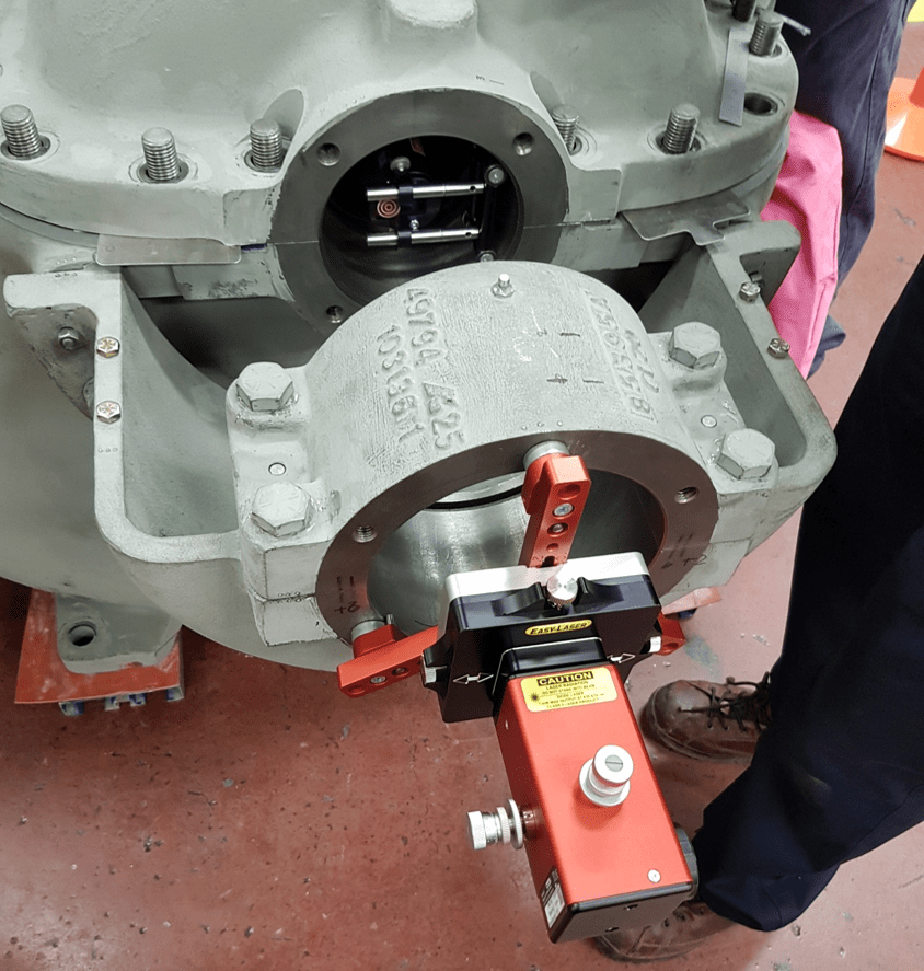
Figure 7
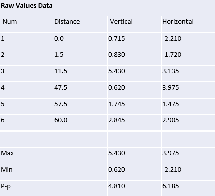
This chart shows the raw values that were taken.
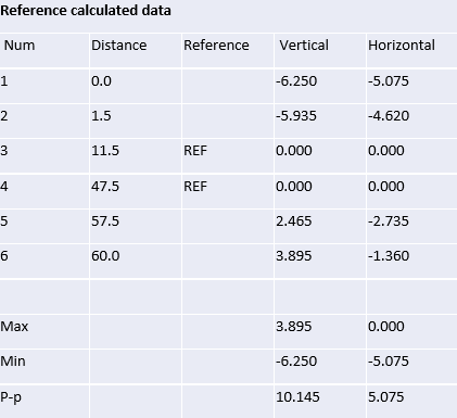
This chart shows the two reference points (point 3 and 4) that have been selected (the stuffing boxes). You can see that the other values have changed and show the precise measured result of the positions of the bearing journals.
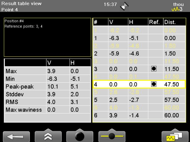
And of course, we measure twice. This last table shows the Straightness program results including the almost perfect repeatability. Using two operators we got the same results.
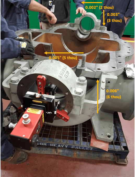
Figure 8 – Please note: this photo shows the laser assembly and analysis stage where the pump is mounted on a pallet. However, the final measurements were taken with the machine placed on a flat base. We also shimmed the lid in order to compensate for the thickness of the gasket before measuring.
After referencing the bearing (stuffing box) points #3 and #4 to zero set, we get our adjustment points at the remaining four points (#1, #2, #5 and #6). If we average the adjustment data for the measurement points at each bearing, you can see in Figure 8 how much we need to move each bearing. Based on zero setting, the stuffing box bearings (#3 & #4), the adjustments would be 2 thou to the left and 3 thou down for the back bearing. For the front bearing (closest to the laser) the adjustment would be 5 thou to the left and 6 thou up. The front bearing was, in the end, adjusted back into the correct position.
Conclusion
As we mentioned before, this is, in essence, the measurement of a straight line. With rotation you can use that measurement to align the bores using two reference points. Measuring straightness comes under geometric measurement. Geometric measurement is the measurement straightness, level, flatness, square, plumb, parallel, etc. We use optical tooling such as lasers to take these measurements. The benefits of lasers are the speed that we can take measurements, the ability to change reference points allowing us to choose the optimal result/adjustment (meaning the least amount of work), greater accuracy that all can see digitally, the lower cost as compared to other optical tooling systems and most importantly, the documentation/report that is required for modern day alignment work.
These types of measurement are not just for bore alignment. Parallel measurements can be used for rolls in Steel Mills and Paper Mills. Squareness measurements can be used to qualify the accuracy of a milling machine in machine shops. We can use flatness to measure a machine base which is probably one of the most important things to do in machinery installation. And there is more a lot more. Have a look at your processes, what do you need to use geometric measurement for?
About Author
0 comments
Write a comment