

PRACTICE MAKES PERFECT – BORE ALIGNMENT USING A SHAFT ALIGNMENT SYSTEM
Recently one of our application experts was asked a question from a colleague on bore alignment. He wanted to know if you could use a shaft alignment system to do bore alignment. The answer was yes, but not without practicing.
He had an EASY-LASER E710 and he needed to do this work quickly so there wasn’t time to get the EASY-LASER E950 Bore alignment system or the bracketing. Our application engineer explained that it is technically doable but not the preferred method. The reason for this, is if you are hand moving both measuring units inside the bore, the chances of you getting repeatability can be very difficult unless you PRACTICE, PRACTICE and then PRACTICE some more.
If you think about bore alignment, it’s really like doing a shaft alignment, but in the inverse. With bore alignment you are measuring the inside circumference of a circle (bore) in the same way as when doing shaft alignment, where you are measuring on the outside of the circle (shaft). So in essence, trying to measure and align two separate bores using a shaft alignment method would be like doing an open coupling shaft alignment when you were unable to rotate the shaft and are sliding the brackets (in the inverse!)
The procedure was written out and sent to the colleague including some photos on the operation. You can do a lot of different measurements with laser alignment tools but you need to know how it is done. Even then you must PRACTICE, PRACTICE and then PRACTICE some more to make sure that you get repeatability. At BENCHMARK PDM, all of our technical support and sales staff are given time to practice the tools they sell and support. If they can’t do it, then how is the customer supposed to!
The most important part is the set up and making sure the actual bracketing being used is positioned correctly while taking the actual measurements. Of course, with any alignment/measurement it is important that the brackets mounting surface is very clean with no nicks or burrs. The ideal bracket would be a sliding bracket small enough to fit in the bore with rods extending out which would hold the measuring unit. This is an accessory and if you don’t have this, you can use the magnet bases the standard E710 system comes with. The bores should also be clean so you can properly maneuver the brackets inside.
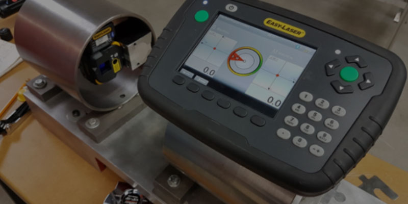
Set-up and Values:
It is extremely important that the mag base or slide bracket sits in the bore properly when taking measurements. If it doesn’t “click” into place, it may give you incorrect readings later. When you set up in the small bore, use the shortest distance of rods possible so it is easier to control. In the larger bore, you may have to use longer rods and move the detector out to the appropriate distance. Make sure to do your rough alignment so your units will be in the detector at all three positions allowing you to measure at 9-12-3 (or 9-6-3). We strongly suggest practicing this in the Values program first to really get the feel for placing the units/brackets at the same position of the bore each time.
Horizontal Program/Set up:
Open the horizontal shaft program and pick your machine images. Place the units in your bores, put your S-M distance in (rod to rod), accept the S-C distance, and then input the feet adjustment distances of the moveable bore machine.
IMPORTANT: normally, when doing a regular shaft alignment, you put the M-F1 (Moveable to Foot 1) distance in as a positive number because the measuring unit is sitting on the shaft before (or inside) the foot. However, in the practice application on the photos below, it was very important we put the M-F1 distance in as a negative number because the unit is sitting behind the adjustment foot.
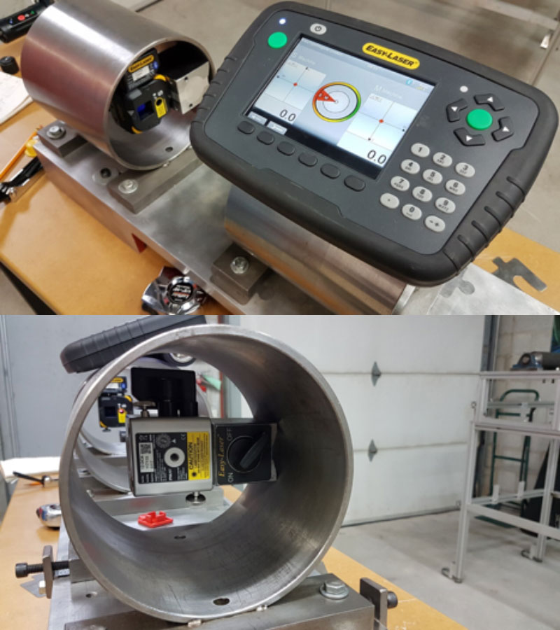
Measurements:
Once in the measurement stage, put both units at your starting position using the inclinometers and measure at the 3 positions.
IMPORTANT: You must always go back to the exact same inclinometer positions every time to get maximum repeatability. Also, it is very important to make sure you place the units at the same position axially (along the length of the bore). In the photos (2 for each unit at each position, 9-12-3), we made sure the magnet base was always flush to the rim of the bore. Take multiple measurements and make sure your numbers are repeating. If they are not, there may have been a mistake along the way.
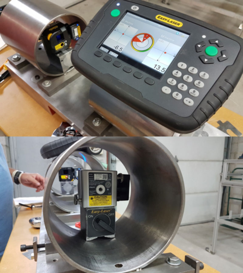

Final Adjustments/Corrections:
If you have got repeatable measurements, you can adjust the same way you would doing a shaft alignment. Once adjusted, take final measurements to make sure you get repeatability. You can see there is a lot of “important” things to do in this type of measurment, but if you practice and make sure to follow the steps, you can get as close to a perfect bore to bore alignment using a shaft alignment system as anyone can.
0 comments
Write a comment