

Understanding Thermal Growth in Your Rotating Machinery – Part 3
There are other issues we should be aware of when talking about a machine’s thermal growth in our rotating machinery and how it affects the machine’s alignment at the coupling. One major factor affecting machinery alignment is Dynamic pipe strain caused by thermal growth. However, there are two types of pipe strain and the other type is also important to know about. Static pipe strain exists when the machines are not even operating. Static pipe strain is a major cause of machine failures and is the result of incorrect fabrication and/or installation, inadequate or missing support, or machine movement after piping is connected. Its effects are relatively simple to measure however, it’s often ignored because repairs or rework are perceived to be costly, but that’s not always the case.
Dynamic pipe strain is much more difficult to measure since it is present only after the machine and piping are at operating conditions. The word dynamic is characterized as constant change or movement (growth or shrinkage) and much of this movement is due to temperature change – hot or cold. If you are involved in some sort of machinery maintenance and repair or a condition monitoring program at your company/plant, you have probably seen some severe cases of machines increasing or decreasing in temperatures. For example, compressors can have ice forming at the inlet (suction) piping whereas the outlet (discharge) piping is often too hot to even touch. So some piping will grow and others may shrink. This is dynamic pipe strain and it can have a lot of influence on your machines.
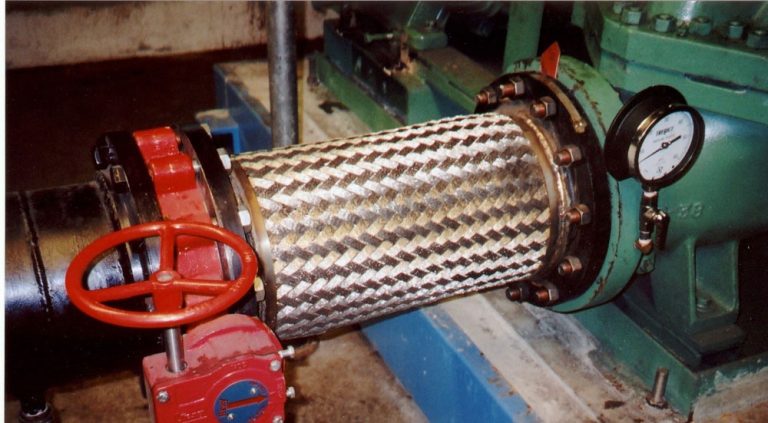
Large temperature changes in piping will have a major effect on the machines they are attached to and usually result in moving these machines out of alignment. OEM (Original Equipment Manufacturers) can give you the expected amount of growth for their machines but in regards to piping, you are on your own. That is why the smart choice is to use flexible pipe joints between the piping system and the machine units (see photo below). Or when a company, such as yours, has something that needs to be processed and manufactured on a large scale, but you don’t have the resources to complete the job in-house, contract processing could be the solution. Firms like Thermograde Process Technology will have all the machinery in place and you don’t have to worry about the piping system or anything for that matter. However, it’s always better to know how all this equipment work.
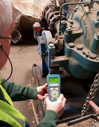 In the following example, we take a temperature reading on the bearing housing of a pump just below the centre line. Pictured on the left, we can see where the laser pointer is for the location of the temperature reading. The reading we get a 171 F.
We know the ambient temperature is 70 F so the temperature difference is 101 F (T). The pump leg is 16 inches long (L) – the height from the foot to the center of the shaft. So if we want to know the thermal expansion of this pump we need to know one more thing: the coefficient of expansion (“/ F). In this example, the coefficient of expansion of mild steel is 0.0000063 (“/ F) (C). We multiply it by the length (height) of the leg (16 inches) and we get 0.0001. Now we multiply this by the temperature difference (101 F) and we have 0.010 inches (10 thou) of growth. Yes, 10 thou is a lot when the offset tolerance for this pump is 2 thou (0.002 inches).
In the following example, we take a temperature reading on the bearing housing of a pump just below the centre line. Pictured on the left, we can see where the laser pointer is for the location of the temperature reading. The reading we get a 171 F.
We know the ambient temperature is 70 F so the temperature difference is 101 F (T). The pump leg is 16 inches long (L) – the height from the foot to the center of the shaft. So if we want to know the thermal expansion of this pump we need to know one more thing: the coefficient of expansion (“/ F). In this example, the coefficient of expansion of mild steel is 0.0000063 (“/ F) (C). We multiply it by the length (height) of the leg (16 inches) and we get 0.0001. Now we multiply this by the temperature difference (101 F) and we have 0.010 inches (10 thou) of growth. Yes, 10 thou is a lot when the offset tolerance for this pump is 2 thou (0.002 inches).
If we add them together and divide by four (4), we get the average of 148 F. When we take away ambient temperature (70 F) we get a temperature difference of 78 F. If we put these numbers into our thermal expansion formula from Part 2 of this article, it looks something like this:
T x L x C
= 78 F x 16″ x 0.0000063″ / F
= 0.007″ (7 thou)
7 thou (using the average of four (4) temperature readings) and 10 thou (using the highest reading) only gives us a difference of 3 thou. Not a lot, but can make a difference when 2 thou is the tolerance.
We take temperature readings and average them for all four feet of each machine. After we input the info into our thermal growth expansion calculation (T x L x C), the results show:
Outboard pump feet – 0.007″ (7 thou) of growth.
Inboard pump feet – 0.006″ (6 thou) of growth.
Inboard motor feet – 0.004″ (4 thou) of growth.
Outboard motor feet – 0.002″ (2 thou) of growth.
If I graph these projections, you can see (below) by the dashed black center lines of each shaft that the offset and angle is very good, so we are in tolerance.
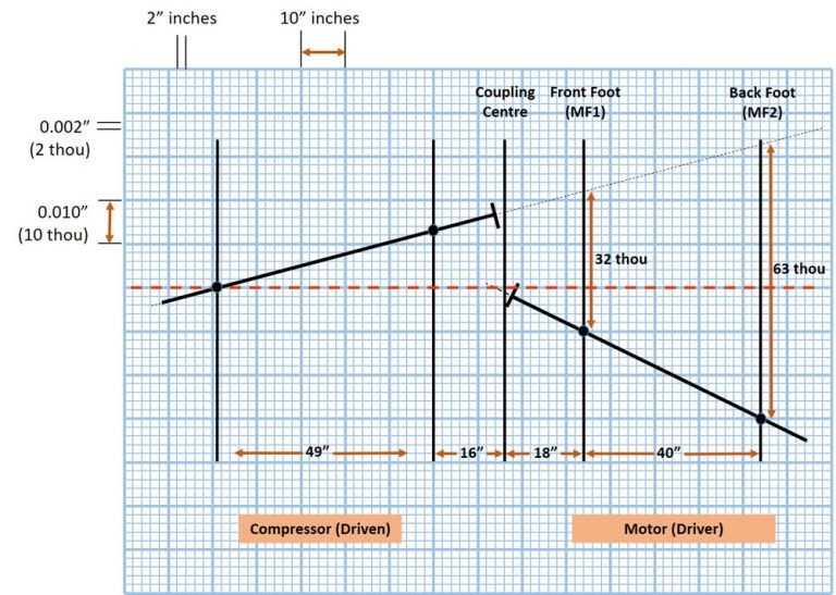
What’s important is if I had based the results on the one highest reading, I would have been out of tolerance. However, by averaging I am good to go. Not taking the correct temperature reading is a common mistake and it does make a difference.
Let’s look at another example. If we take temperature readings in the plane of the foot at the outlet of this blower (pictured below) we get 150 F, 150 F, 149 F and 146 F. The average of these readings becomes aprrox. 148 F. The ambient temperature is 75 F giving us a difference of 73 F. If we use the coefficient of expansion of mild steel 0.0000063 (“/ F) (C) and multiply it by 18 inches (L) – the height from the foot to the center of the shaft – and the temperature change (T x L x C), we should have 0.008″ (8 thou) of thermal expansion/growth at the outlet.
The inlet has much lower readings of 67 F, 69 F, 78 F and 84 F. The average of this is 74 F. Taking away the ambient temperature, we get a difference of -1 F. If we do the thermal growth calculation (T x L x C) we have no growth. After doing a thermal growth calculation for the motor, we found that the results for the inboard feet were 0.003″ (3 thou) of growth and the outboard feet was 0.002” (2 thou) of growth. This means that the outlet of the blower would grow, tilting the shaft down at the coupling, putting the machine out of alignment.
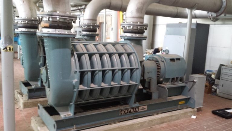
Attached to the machine is the OEM (Hoffman) guide to compensating for thermal growth of the Blower. After some pre-alignment checks, at # 5 it says to align the driver shaft (motor) parallel to the blower shaft (driven).
Then at # 5A, it says to add 0.008″ (8 thou) of shim to all the motor feet lifting it up.
At # 5B it says to add .012″ (12 thou) to the inlet end of the blower.
Finally, at # 5C, it says that a hot alignment measurement and correction must be done after the machine has been run up to full operating temperature.
To see this visually we can make a simple graph. The scale that we use is that each small box in the horizontal plane (going across the page) represent 2 inches. For the vertical plane each small box (going up and down the page) represents 0.002″ inch (2 thou).
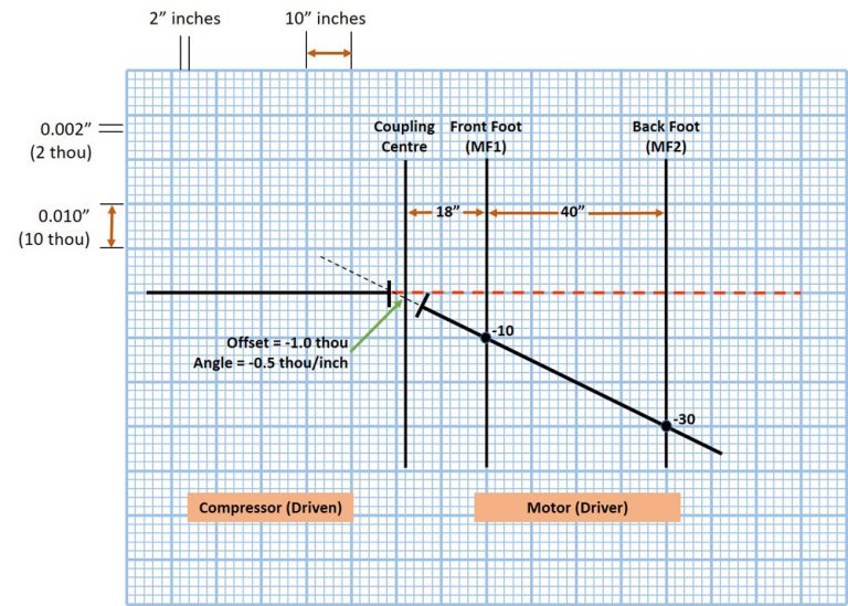
On the OEM guide, # 5 says to align the shaft which we have shown using the two black shafts along the red dotted line.
Then #5A and 5B said to add 0.008″ (8 thou) to all of the motor’s feet and 0.012″ (12 thou) to the inlet feet set of the blower. This you can see is represented by the red shafts for each machine.
Once the machine unit is started and runs up to full operating temperature, we can take the measurements and then calculate the thermal growth based on these measurements. We get 0.008″ (8 thou) at the outlet, 0.000″ (0 thou) at the inlet, 0.003″ (3 thou) at the motor front feet and 0.002″ (2 thou) at the back feet. These growth numbers are represented by the green shaft and as you can see, it is very close to being within tolerance.
By doing a hot alignment (#5 C on the OEM guide) we will be able to trim this so that it’s a precision alignment. We think this is great information supplied by the OEM (Hoffman). You will not always have all the information you need to be able to get a good alignment with this guide because of, for example, what the ambient temperature is or the temperature of the air going into the inlet. However, based on a mechanic/millwrights experience with this machine the guide can give you a very good estimate so that you will be close at start up.
 What we have been doing is giving you a practical look at thermal growth. How to be able to measure and calculate how much it will grow using a simple formula. The graph is a helpful way to see the machine’s growth visually. Its not an exact science however, it will get you very close. The reason why it is not exact is because of all the variables associated with the machine unit that can have an effect. We have already gone through some of them including pipe strain, incorrect temperature measurement readings, and following the proper OEM guides. Some others include the size of the machines feet, the design of the casing, and the airflow in and around the machine. Measuring thermal growth can he difficult with all of these variables influencing the machine unit, but it’s a lot better than the alternative – which is to ignore it!
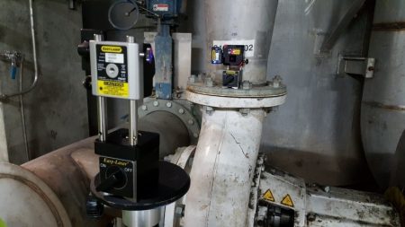
Our professional level shaft alignment system can measure live time movement of the machines with specialized brackets attached to the machines. It can also give you live time readings in both the horizontal and vertical planes when mounted on a pipe as shown below left.
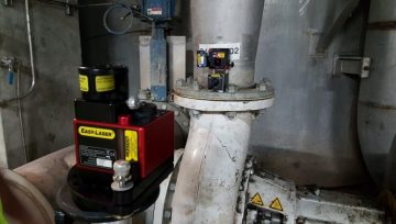 All of our shaft systems can give live time readings that can be used to measure pipe stress; for instance, when connecting or disconnecting piping. In fact, there are a lot of ways to measure machine movement because of thermal growth and machine casing stress, such as optical instruments or even inside micrometers and tooling ball set ups. We can also use geometric lasers to measure (photo above right). However, to set this type equipment up is time consuming and expensive. It is justifiable if there are issues with the machines but for the average machine this is not done. That is why we recommend a thermal growth calculation as well as a hot alignment measurement.
A hot alignment check is recommended by many OEM’s as part of their initial installation procedure. However, some companies tend to not do it as it is perceived as being unsafe. This is because the measurement should be done as quickly as you can after the machine unit is shut down. This does not mean that you have to be working in an unsafe manner. It does mean that it should be well planned and that all safety requirements are followed in a controlled manner. Yes, the machine will be hot so care does have to be taken – but as maintenance professionals, it’s what we do! I would like to make note that before this type of work is attempted, it should be reviewed by a safety committee so that all are aware of the requirements, procedures, etc.
Again, doing a hot alignment is not an exact science because there are many variables. I know some companies who will do one as soon as the machines are at operating temperature, then do another a day later just to confirm. For instance, thermal changes in gearboxes can be very difficult to calculate. Many large gearboxes will grow in the horizontal plane as well as the vertical plane. So a hot alignment would be seen as the best way to do this work. This article is intended to give you some idea of thermal growth and some simple ways on how to measure it, graph it and understand some of the major factors contributing to it ie. pipe strain. It was written to bring a better awareness of this issue and how using some simple tips such as where to take proper temperature measurements while using an average and taking note of OEM guides, can help in the overall alignment process. These are things that we don’t often consider. Its not written to cover some of the more complex challenges that exist on some machines with very high operating temperature. One would expect that the machine manufacturer would have a documented procedure for such a machine. And if not, laser real time measurement would be taken in order to see the actual machine movement.
0 comments
Write a comment